Shoot control method and device

A control method and object technology, which are applied in the directions of image communication, TV, color TV components, etc., to achieve the effect of rapid judgment and accurate zooming, and avoiding zoom processing operations.

Inactive Publication Date: 2013-04-17
GUANGDONG OPPO MOBILE TELECOMM CORP LTD
View PDF4 Cites 29 Cited by
  • Summary
  • Abstract
  • Description
  • Claims
  • Application Information

AI Technical Summary

Problems solved by technology

[0003] The purpose of the embodiments of the present invention is to provide a camera control method and device, aiming to solve the problem that the distance between the subject and the photographer is constantly changing when the user is using the camera terminal. The cumbersome steps of non-stop zooming o...

Method used


Image

  • Shoot control method and device
  • Shoot control method and device
  • Shoot control method and device

Examples


Embodiment 1

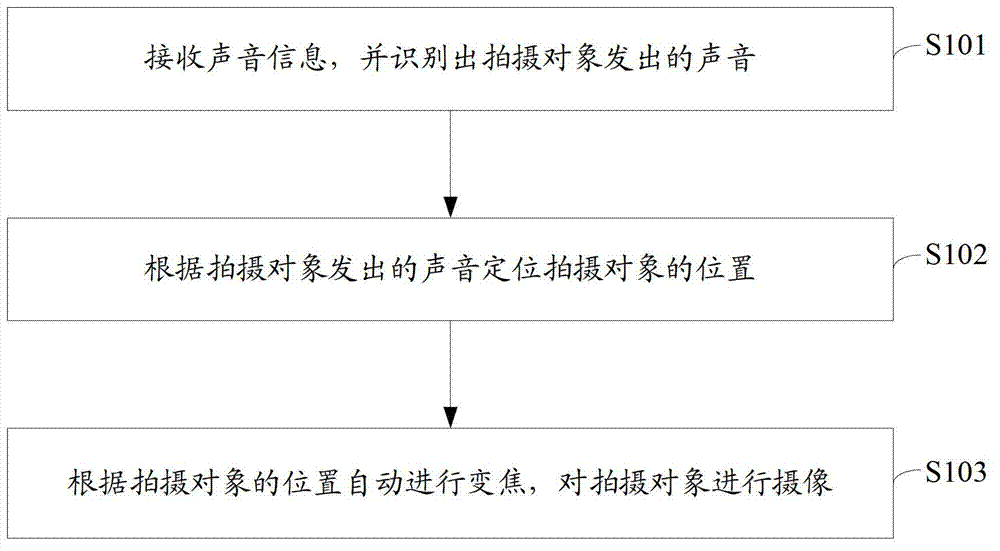
[0048] figure 1 The implementation flow of a camera control method provided by the first embodiment of the present invention is shown, and the details are as follows:

[0049] S101. Receive sound information, and recognize a sound from a shooting object.

[0050] The sound from the subject is received, and at the same time, the sound from the subject is recognized from all the received sound information. Specifically, the sound of the subject is identified by means of sound frequency comparison.

[0051] S102. Locate the position of the photographed subject according to the sound emitted by the photographed subject.

[0052] According to the recognized sound of the subject, the source of the subject's sound is located, so as to find out the position of the subject, specifically, the sound is received through multiple microphones, and the time sequence of receiving the sound through different microphones and the position of the microphone are calculated. Where the subject is ...

Embodiment 2

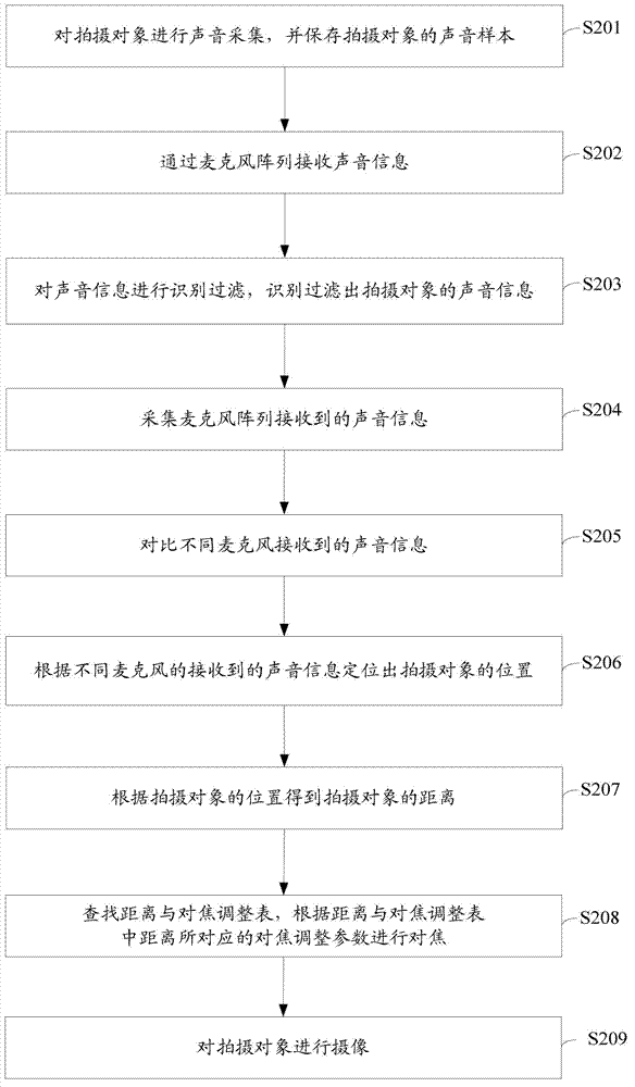
[0057] figure 2 The implementation flow of a camera control method provided by the second embodiment of the present invention is shown, and the details are as follows:

[0058] S201. Collect the sound of the object to be photographed, and save the sound sample of the object to be photographed.

[0059] First, the sound of the subject is collected, the sound sample of the subject is collected, and the sound sample is saved at the same time.

[0060] S202. Receive sound information through a microphone array.

[0061] The sound information is received through a microphone array. The specific microphone array can be at least two or more microphones. The sound information is collected through two or more microphones, and the positioning is performed according to the time difference of different microphones collecting sound information. The number of specific microphone arrays Custom adjustments are available.

[0062] S203. Identify and filter the sound information, and identi...

Embodiment 3

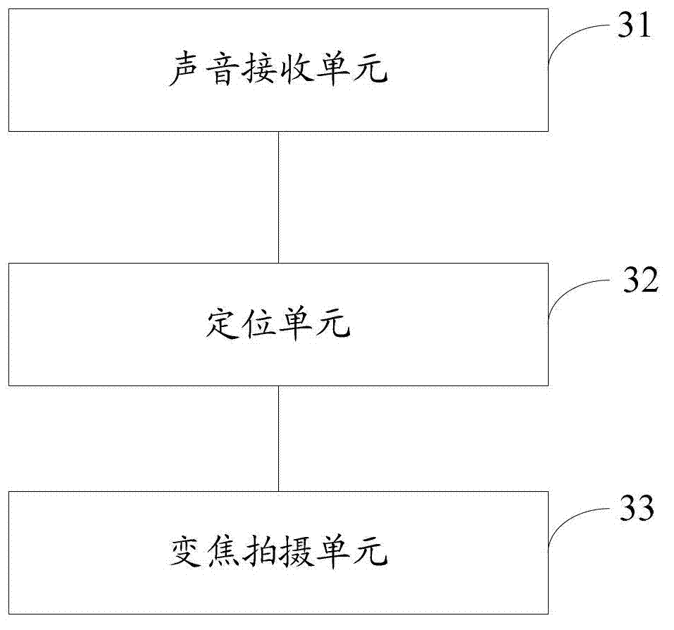
[0078] image 3 A structural diagram of an imaging control device provided by a third embodiment of the present invention is shown, and for convenience of description, only parts related to the embodiment of the present invention are shown.

[0079] The sound receiving unit 31 is configured to receive sound information and recognize the sound made by the subject.

[0080] The sound receiving unit receives sound, filters and recognizes the received sound, and recognizes the sound of the shooting object. Specifically, multiple microphones are used for receiving.

[0081] The positioning unit 32 is configured to locate the position of the photographed subject according to the sound emitted by the photographed subject.

[0082] The positioning unit calculates according to the sound emitted by the photographed object, locates the position of the photographed object according to the sounds received by a plurality of different microphones, and realizes the judgment and determinatio...


PUM


Abstract

The invention is suitable for the field of traveling shoot, and provides a shoot control method and a shoot control device. The method comprises the following steps of: receiving sound information and identifying a sound made by a shot object; positioning the shot object according to the sound made by the shot object; and automatically zooming according to the position of the shot object, and shooting the shot object. According to the method, the distance position of the shot object is judged by receiving the sound of the shot object, the need of performing zooming processing is judged according to the distance position of the shot object, and automatic zooming processing is performed under the condition that zooming processing is needed, so that the shot object is positioned at the shooting zooming position of a lens in a shooting process, a user does not need to zoom manually, and complex zooming operation is avoided; and meanwhile, rapid judgment and accurate zooming can be performed by zooming according to sounds.

Description

technical field [0001] The invention belongs to the field of camera terminals, and in particular relates to a camera control method and device. Background technique [0002] When the current digital camera or terminal camera takes a video or takes a picture, it is usually necessary to manually adjust the focal length to control it. However, in some scenes, such as mobile camera, such an operation is inconvenient, because in a moving scene, the object to be photographed is constantly moving, and the focus needs to be adjusted continuously, and the operation is cumbersome. Contents of the invention [0003] The purpose of the embodiments of the present invention is to provide a camera control method and device, aiming to solve the problem that the distance between the subject and the photographer is constantly changing when the user is using the camera terminal. The cumbersome steps of non-stop zooming operation, by adopting the camera control method provided by the present...

Claims


Application Information

Patent Timeline
IPC IPC(8): H04N5/232
Inventor 曾元清
Owner GUANGDONG OPPO MOBILE TELECOMM CORP LTD
Why Eureka
Try Eureka