

Parallel mechanism
A drive mechanism, parallel link technology, applied in the direction of manipulators, mechanical equipment, program-controlled manipulators, etc., can solve the problem of difficulty in achieving high speed and high precision at the same time
- Summary
- Abstract
- Description
- Claims
- Application Information
AI Technical Summary
Problems solved by technology
Method used
Image

Examples
no. 1 Embodiment approach
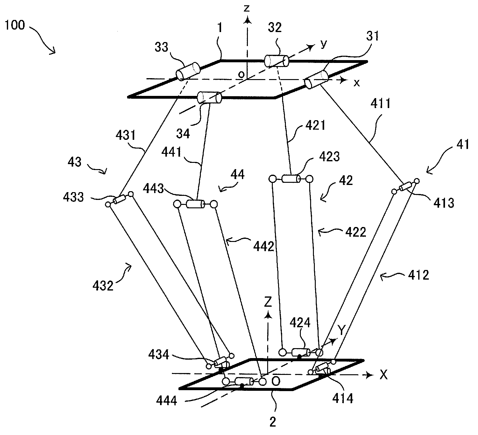
[0029] Hereinafter, the first embodiment will be described with reference to the drawings. This embodiment constitutes a parallel mechanism 100 driven by four degrees of freedom.
[0030] Such as figure 1 As shown, the parallel mechanism 100 of this embodiment has a fixed plate 1 , four rotary actuators 31 , 32 , 33 , 34 , four peripheral drive mechanisms 41 , 42 , 43 , 44 and a movable plate 2 . Hereinafter, in order to facilitate the description of the configuration of the mechanism, etc., the absolute coordinates (xyzo) are set in such a way that the center of the fixed plate 1 is taken as the origin o and the xoy plane is parallel to the fixed plate 1, and the center of the movable plate 2 is taken as The relative coordinates (XYZO) are set so that the origin O and the XOY plane are parallel to the movable plate 2 .
[0031] The rotary actuators 31 and 33 are arranged on the x-axis so that they are symmetrical with respect to the absolute coordinate origin o and their re...
no. 2 Embodiment approach
[0056] Next, a second embodiment will be described with reference to the drawings. This embodiment constitutes a parallel mechanism 1000 driven with 6 degrees of freedom (the movable plate is driven with 5 degrees of freedom, and the end effector is driven with 1 degree of freedom).
[0057] Such as Figure 6 As shown, the parallel mechanism 1000 of this embodiment has a fixed plate 1001 , four peripheral drive mechanisms 1041 to 1044 , a central drive mechanism 1005 , a movable plate 1002 and an end effector 1003 . Also in this embodiment, the absolute coordinates are set so that the center of the fixed plate 1001 is the origin o and the xoy plane is parallel to the fixed plate 1001 in order to facilitate the description of the arrangement of the mechanism, etc., as in the above-mentioned first embodiment. (xyzo), relative coordinates (XYZO) are set so that the center of the movable plate 1002 is the origin O and the XOY plane is parallel to the movable plate 1002 .
[0058...
no. 3 Embodiment approach
[0088] Next, a third embodiment will be described with reference to the drawings. This embodiment constitutes a parallel mechanism 2000 driven by 6 degrees of freedom (the movable plate is driven by 4 degrees of freedom, and the end effector is driven by 2 degrees of freedom).
[0089] Such as Figure 12 As shown, the parallel mechanism 2000 of this embodiment has a fixed plate 2001 , four peripheral drive mechanisms 2041 to 2044 , a central drive mechanism 2005 , a movable plate 2002 , a differential mechanism 2100 and an end effector 2003 . The end effector 2003 is provided below the movable plate 2002 so as to be rotatable around the first rotation axis 2104 . In addition, in this embodiment, the absolute coordinates (xyzo) are set so that the center of the fixed plate 2001 is the origin o and the xoy plane is parallel to the fixed plate 2001, so that the center of the movable plate 2002 is the origin O, And the relative coordinates (XYZO) are set in such a way that the X...
PUM
 Abstract
Description
Claims
Application Information