Image encoding method and image encoding device
An image coding and coding technology, which is applied in the field of image decoding and can solve the problem of ineffective transmission of segmentation information.
- Summary
- Abstract
- Description
- Claims
- Application Information
AI Technical Summary
Problems solved by technology
Method used
Image

Examples
Embodiment 1)
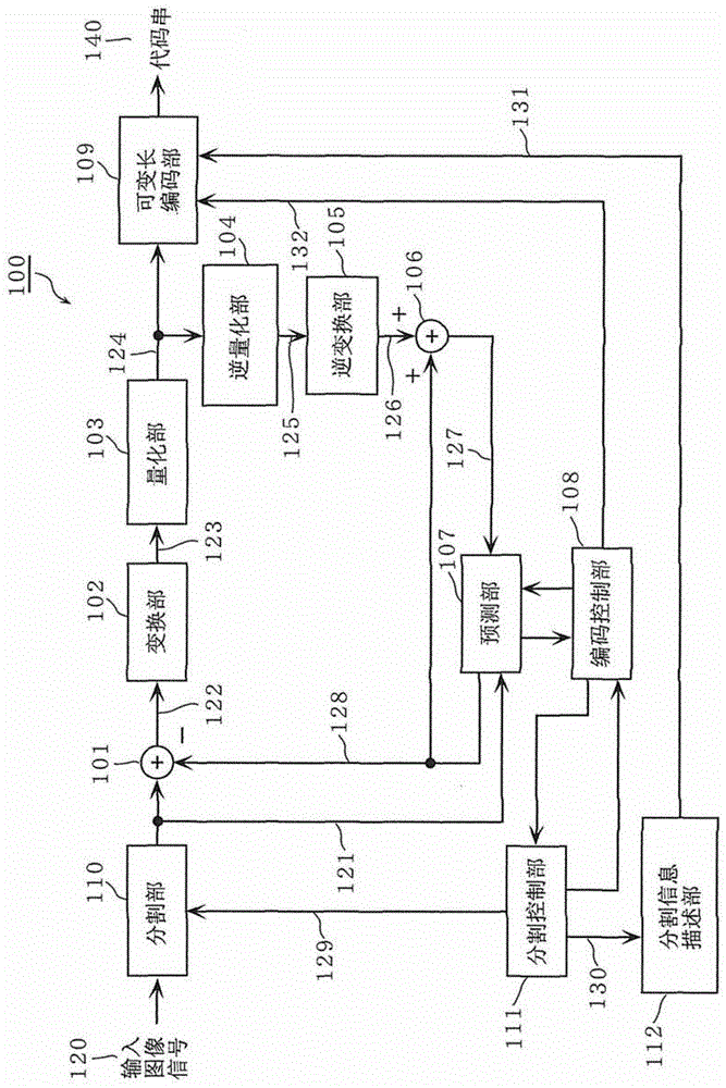
[0090] figure 1 It is a block diagram of the image coding apparatus 100 using the image coding method according to Embodiment 1 of the present invention. figure 1 The illustrated image encoding device 100 divides an input image signal 120 into processing units (blocks), encodes the divided image, and generates a code string 140 .
[0091] The image encoding device 100 includes a difference unit 101, a transform unit 102, a quantization unit 103, an inverse quantization unit 104, an inverse transform unit 105, an addition unit 106, a prediction unit 107, an encoding control unit 108, a variable length encoding unit 109, A division unit 110 , a division control unit 111 , and a division information description unit 112 . In addition, the division unit 110 and the prediction unit 107 may include internal memories.
[0092] The input image signal 120 is input to the division unit 110 . The division unit 110 divides the input image signal 120 according to the division control si...
Embodiment 2)
[0171] In Embodiment 2 of the present invention, an image decoding device 200 that decodes the code string 140 generated by the image encoding device 100 described above will be described.
[0172] Figure 7 It is a block diagram of the image decoding device 200 using the division information restoring unit 207 according to the present embodiment. Figure 7 The illustrated image decoding device 200 includes a variable length decoding unit 201 , a decoding control unit 202 , an inverse quantization unit 203 , an inverse transformation unit 204 , a prediction unit 205 , an addition unit 206 , and a division information restoration unit 207 . In addition, the prediction unit 205 may include a memory inside.
[0173] The code string 140 is a code string generated by the image coding device 100 according to Embodiment 1 of the present invention. This code string 140 is input to the variable length decoding unit 201 .
[0174] The variable length decoding unit 201 decodes divisio...
Embodiment 3)
[0190] In this embodiment, the description will be made on the case where the division information description unit 112 predicts the division pattern.
[0191] The division information description unit 112 estimates a predicted division pattern that is a predicted value of the division pattern of the block to be processed by using the division pattern of the already coded block. Furthermore, the partition control unit 111 determines the partition pattern of the block to be processed using the estimated predicted partition pattern.
[0192] In addition, the division information description unit 112 may estimate the division pattern of the block to be processed by using the division pattern of a block adjacent to the block to be processed in the same frame as the block to be processed, or may use other blocks temporally included. The division pattern of the block in the frame is used to estimate the division pattern of the block to be processed.
[0193] First, use Figure 9A ...
PUM
 Abstract
Description
Claims
Application Information
 - R&D
- Intellectual Property
- Life Sciences
- Materials
- Tech Scout
- Unparalleled Data Quality
- Higher Quality Content
- 60% Fewer Hallucinations
Browse by: Latest US Patents, China's latest patents, Technical Efficacy Thesaurus, Application Domain, Technology Topic, Popular Technical Reports.
© 2025 PatSnap. All rights reserved.Legal|Privacy policy|Modern Slavery Act Transparency Statement|Sitemap|About US| Contact US: help@patsnap.com