Injection molding machine

A technology of injection molding machine and body, which is applied in the field of injection molding devices, can solve problems such as safety accidents, safety doors not installed, and inconvenient unloading of injection molding products, and achieve the effects of improving safety, improving work efficiency, and saving time

Inactive Publication Date: 2013-04-24
宁波海晶塑机制造有限公司
View PDF0 Cites 2 Cited by
  • Summary
  • Abstract
  • Description
  • Claims
  • Application Information

AI Technical Summary

Problems solved by technology

[0002] The existing injection molding machines do not install safety doors or use fixed fences in front of them. During the processing, it is easy to cause some safety accidents, and it is also inconvenient to unload the injection molding products.

Method used


Image

  • Injection molding machine
  • Injection molding machine

Examples


Embodiment

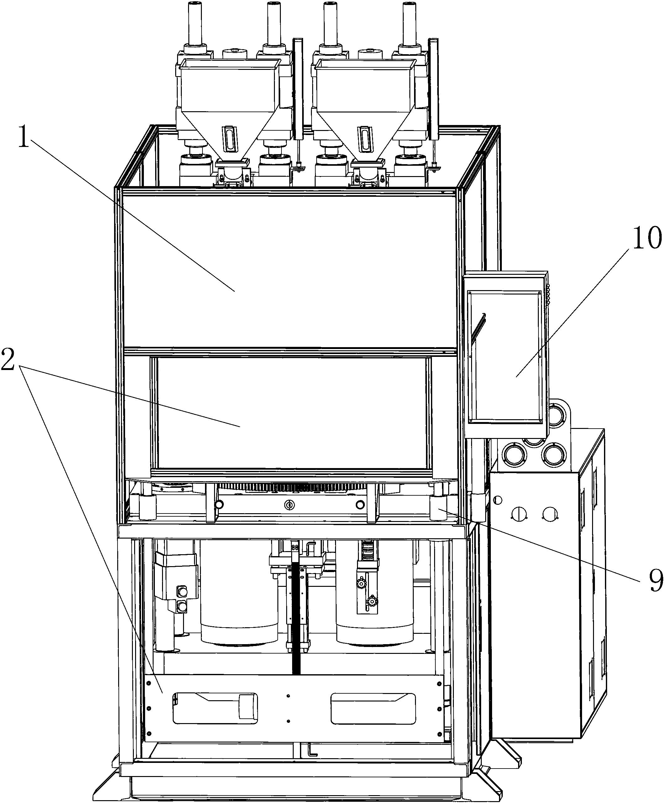
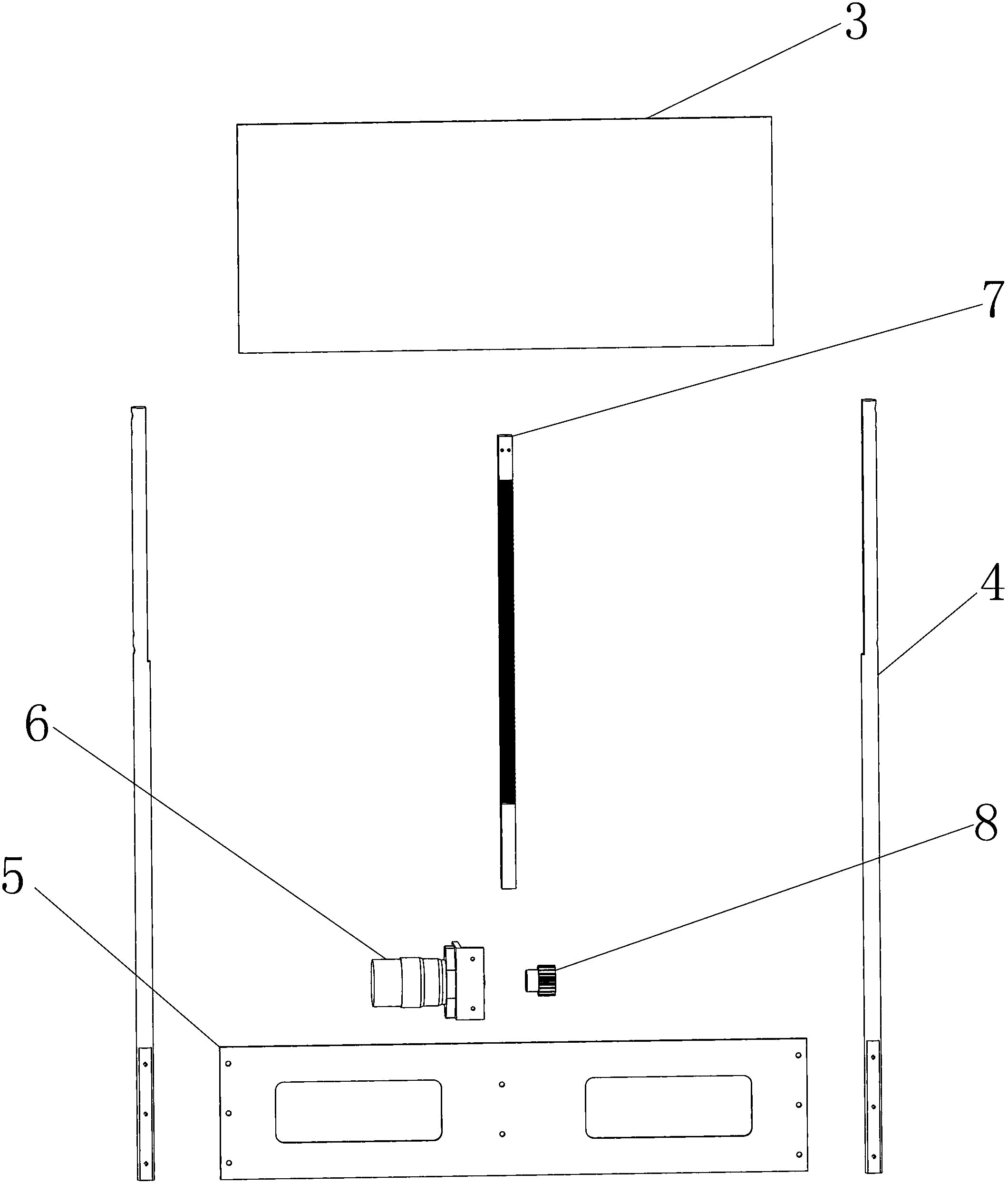
[0014] Example: such as Figures 1 to 2 As shown, the injection molding machine of the present invention includes an injection molding machine body 1, wherein a semi-automatic safety door device 2 is arranged on the above-mentioned injection molding machine body 1, and a controller 10 is installed on the above-mentioned injection molding machine body 1, and the above-mentioned controller 10 controls the semi-automatic safety door The device 2 moves up and down; the semi-automatic safety door device 2 includes a safety door 3, a lifting column 4, a lifting plate 5, a lifting motor 6 and a rack 7; the valve 3 is fixedly connected to the lifting column 4; the lifting column 4 is connected to the injection molding machine body 1 Sleeve fit, the lower end of the lifting column 4 is fixedly connected with the lifting plate 5; the lifting motor 6 is assembled on the lifting plate 5, and the lifting motor 6 is provided with a gear 8; the rack 7 is installed on the body 1 of the injecti...


PUM


Abstract

The invention relates to an injection molding machine. The injection molding machine comprises an injection molding machine body. The injection molding machine body is provided with a semi-automatic safety gate device. A controller is installed on the injection molding machine body. The controller controls the semi-automatic safety gate device to move upward / downward. The semi-automatic safety gate device comprises a safety gate, lifting stand columns, a lifting plate, a lifting motor and a rack. The safety gate is fixedly connected to the lifting stand columns. The injection molding machine body is sleeved on the lifting stand columns. Lower ends of the lifting stand columns are fixedly connected to the lifting plate. The lifting motor is installed on the lifting plate. The lifting motor is provided with a gear. The rack is installed on the injection molding machine body. The gear engages with the rack. The injection molding machine utilizes the semi-automatic safety gate device thereby greatly improving use safety. Lifting of the semi-automatic safety gate device and operation of the injection molding machine are carried out synchronously so that operation time is reduced and work efficiency is improved.

Description

technical field [0001] The invention relates to an injection molding device, in particular to an injection molding machine. Background technique [0002] Existing injection molding machines do not install safety doors or use fixed fences in front of them. During the processing, it is easy to cause some safety accidents, and it is also inconvenient to unload injection molding products. Contents of the invention [0003] 1. Technical problems to be solved [0004] The purpose of the present invention is to solve the above-mentioned problems existing in the prior art, and to provide an injection molding machine. By setting and installing a semi-automatic safety door device at the front end of the injection molding machine body, the safety of the production and processing process is greatly improved. In addition, the semi-automatic safety door device The status is opened and closed synchronously, which improves the work efficiency of this link. [0005] 2. Technical solution...

Claims


Application Information

Patent Timeline
Patent Type & Authority Applications(China)
IPC IPC(8): B29C45/84
Inventor 袁玲才
Owner 宁波海晶塑机制造有限公司
Why Eureka
Try Eureka