Vertical rotation pay-off stand

The technology of a vertical rotating and pay-off rack is applied in the direction of conveying filamentous materials, thin material handling, transportation and packaging, etc. It can solve the problems of inner wire rod extrusion, pulling down the pay-off rack, hidden dangers, etc. Achieving the effect of avoiding pressure line, facilitating production, convenient, efficient and smooth centralized pay-off

Inactive Publication Date: 2013-04-24
SHANDONG DAYE
View PDF0 Cites 5 Cited by
  • Summary
  • Abstract
  • Description
  • Claims
  • Application Information

AI Technical Summary

Problems solved by technology

If the pay-off cannot be carried out smoothly, it will cause the inner pressure line o

Method used


Image

  • Vertical rotation pay-off stand

Examples


Embodiment Construction

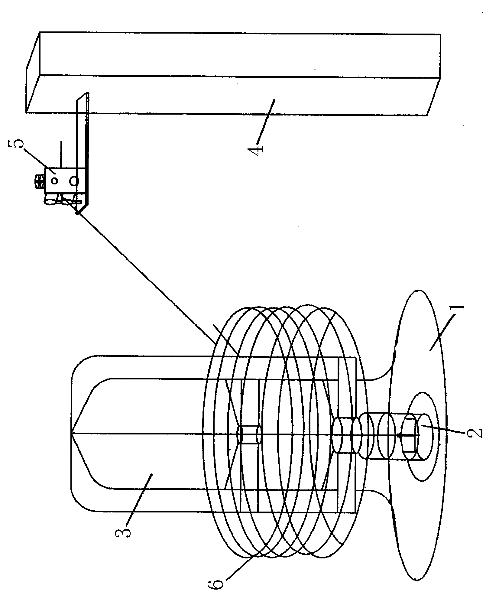
[0009] Such as figure 1 As shown, the present invention supports a pay-off frame 3 through a rotating shaft 2 in the middle of the chassis 1, a support 4 is arranged on one side of the pay-off frame 3, and a pull-out universal wheel 5 is provided at the upper end of the support 4. Through the above settings, the present invention is used for the pay-off of the bead wire rod 6, the bead wire wire rod 6 is connected to the production line via the drawing universal wheel 5, and the production line draws the bead wire wire rod 6 through the drawing universal wheel 5 , At the same time, the pay-off frame 3 realizes rotating and releasing the bead wire wire rod 6 under the action of the pulling force, which avoids the phenomenon of crimping and squeezing the wire, and improves the safety of production.


PUM


Abstract

The invention discloses a vertical rotation pay-off stand which is characterized in that the pay-off stand is arranged in the middle of a base plate and supported by a spindle, a bracket is arranged on one side of the pay-off stand, and a drawing universal wheel is arranged on the upper end of the bracket. The vertical rotation pay-off stand is used for paying off of tire bead steel wire rods, convenient efficient smooth centralized paying-off is achieved, paying-off restraining and locking are avoided, and the pay-off stand is easy to produce.

Description

technical field [0001] The invention relates to a vertical rotary pay-off frame used in a bead steel wire centralized pretreatment production line. Background technique [0002] During the centralized pretreatment of bead wire wire rod, since the pay-off of the centralized processing procedure involves a large number of wire rods being arranged side by side and carried out simultaneously, whether the pay-off can be carried out easily, efficiently and smoothly is the key to whether the whole processing line can be processed smoothly. If the pay-off cannot be carried out smoothly, it will cause the inner pressure line of the wire rod to be squeezed. Even pull down the pay-off frame, causing a safety hazard. Contents of the invention [0003] The object of the present invention is to provide a vertical rotary pay-off stand capable of compact structure in centralized pretreatment, simple pay-off, high efficiency and smoothness. [0004] In order to achieve the above object, ...

Claims


Application Information

Patent Timeline
IPC IPC(8): B65H49/30B65H57/14
Inventor 窦勇王金武李文军
Owner SHANDONG DAYE
Why Eureka
Try Eureka