
Method for Determining Rotation Radius of Crankshaft of Hot-rolled Section Steel Flying Shear Drive

A crankshaft rotation radius and determination method technology, which is applied in special data processing applications, instruments, electrical digital data processing, etc., can solve the problem of affecting the cutting effect of flying shears, the quality of section steel sections, the inability to achieve precise control of flying shears transmission system, and affecting production capacity And other issues

Active Publication Date: 2016-06-29
WISDRI ENG & RES INC LTD
View PDF5 Cites 0 Cited by
  • Summary
  • Abstract
  • Description
  • Claims
  • Application Information

AI Technical Summary

Problems solved by technology

These are all lacking the guidance of systematic theoretical calculation methods, which may easily lead to the unreasonable design of the system inertia and the inability to achieve precise control of the flying shear transmission system, and may also cause a gap between the horizontal speed of the shear blade and the running speed of the rolled section when the shear begins to shear. Large and large differences, which seriously affect the shearing effect of flying shears and the quality of section steel sections, and may also affect production capacity

Method used


Image

  • Method for Determining Rotation Radius of Crankshaft of Hot-rolled Section Steel Flying Shear Drive
  • Method for Determining Rotation Radius of Crankshaft of Hot-rolled Section Steel Flying Shear Drive
  • Method for Determining Rotation Radius of Crankshaft of Hot-rolled Section Steel Flying Shear Drive

Examples


Embodiment Construction

[0158] In order to facilitate a further understanding of the method of the present invention, preferred embodiments are described in detail below in conjunction with the accompanying drawings.

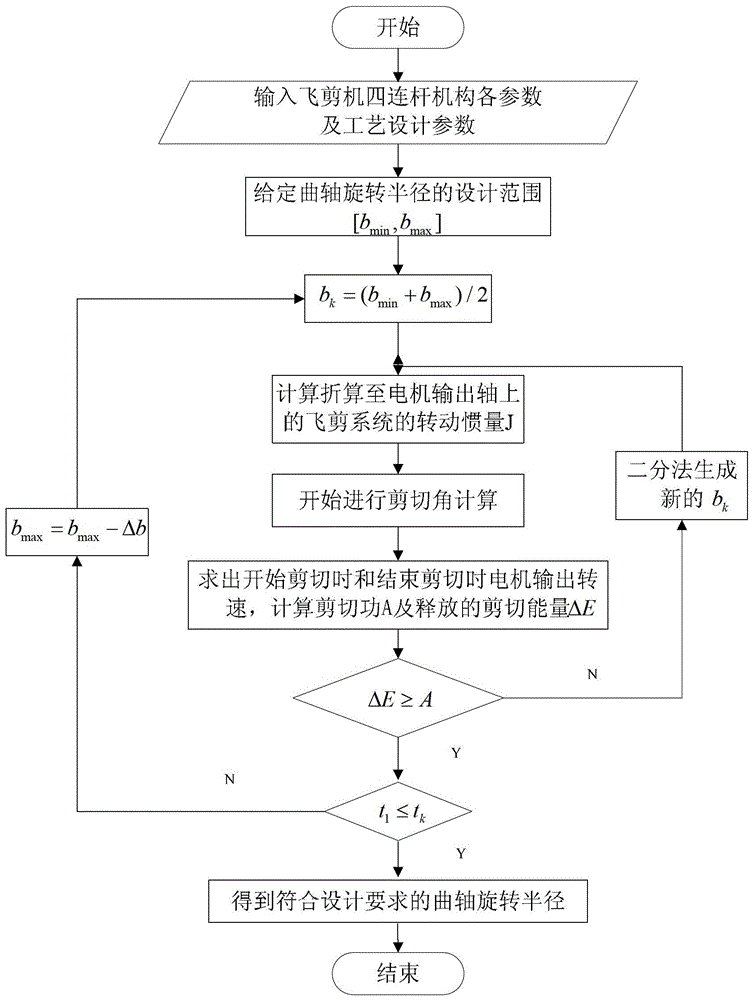
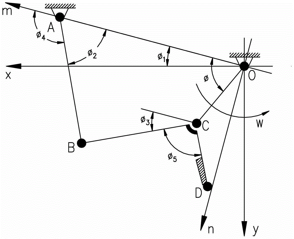
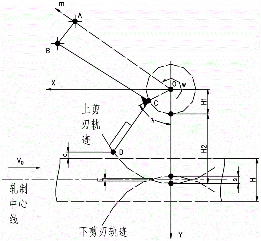
[0159] The method for determining the radius of rotation of the crankshaft of the hot-rolled section steel flying shear transmission crankshaft provided by the present invention firstly determines the radius of rotation of the crankshaft, and then manufactures the transmission crankshaft according to the length of each crankshaft. The flow process is as follows figure 1 As shown, it specifically includes the following steps:

[0160] Step 1: Establish the corresponding coordinate system mon and coordinate system xoy. And according to the parameters to establish the relevant parameter equations in line with the mechanical principle. Given the relevant parameters of each component of the hot-rolled flying shear structure: the length of the fixed frame OA, the length of the connecting ro...


PUM


Abstract

The invention relates to a hot-rolled section steel fly shear transmission crankshaft preparation method. The method is characterizing by firstly determining rotational radiuses of crankshafts and then preparing a transmission crankshaft according to the length of each crankshaft. The method mainly includes following steps: establishing a fly shear four-connecting-rod mechanism space coordinate system, and calculating corresponding rotational inertia under rotational radiuses of each crankshaft and total rotational inertia, of a fly shear system, reduced on a motor output shaft; obtaining space movement track of an upper shear blade point and solving shear angle under a rotational radius of a crankshaft corresponding to a shear blade; and sequentially performing fly shear shearing force energy parameter checking and motor start time restraint condition checking through solved results of motor output rotation speed until obtaining a fixed crankshaft rotational radium meeting requirements. By the method, various uncertain boundednesses caused by geometric construction are completely abandoned, and the hot-rolled section steel fly shear transmission crankshaft is high in generality, adaptiveness, speed and calculating accuracy and capable of serving as a powerful tool for model selection and checking of hot-rolled fly shear motors.

Description

technical field [0001] The invention relates to a method for determining the radius of rotation of a hot-rolled section steel flying shear drive crankshaft, in particular to a method for preparing a fly shear drive crankshaft by determining the radius of rotation of the crankshaft. Background technique [0002] Flying shear is one of the important equipment in the steel rolling production line. It is arranged in front of the finishing rolling unit. It is used for cutting and breaking the head and tail of the rolled material during the hot rolling of section steel. It also has the function of segmentation to prepare for further rolling. , the quality of its working performance directly affects the production efficiency of the rolling line and the quality of the product cut. With the development of continuous rolling mills, flying shears have been used more and more widely. [0003] After the configuration of the crank-link type steel flying shear system and the design of eac...

Claims


Application Information

Patent Timeline
Patent Type & Authority Patents(China)
IPC IPC(8): G06F19/00
Inventor 严国平许燚罗新华董义君
Owner WISDRI ENG & RES INC LTD
Learn More