Fluid supply apparatus and system and method for cleaning thin plate using same

A fluid supply and fluid technology, applied in the field of fluid supply devices, can solve problems such as the influence of the film 4, and achieve the effects of solving film damage or defective products, reducing pressure deviation, and preventing the film from sagging or bending

Active Publication Date: 2013-05-01
LG CHEM LTD
View PDF8 Cites 7 Cited by
  • Summary
  • Abstract
  • Description
  • Claims
  • Application Information

AI Technical Summary

Problems solved by technology

This phenomenon, which is the case where the film 4 enters the next stage in a folded state on the roller 9, can have serious consequences when the film 4 breaks

Method used


Image

  • Fluid supply apparatus and system and method for cleaning thin plate using same
  • Fluid supply apparatus and system and method for cleaning thin plate using same
  • Fluid supply apparatus and system and method for cleaning thin plate using same

Examples


experiment example

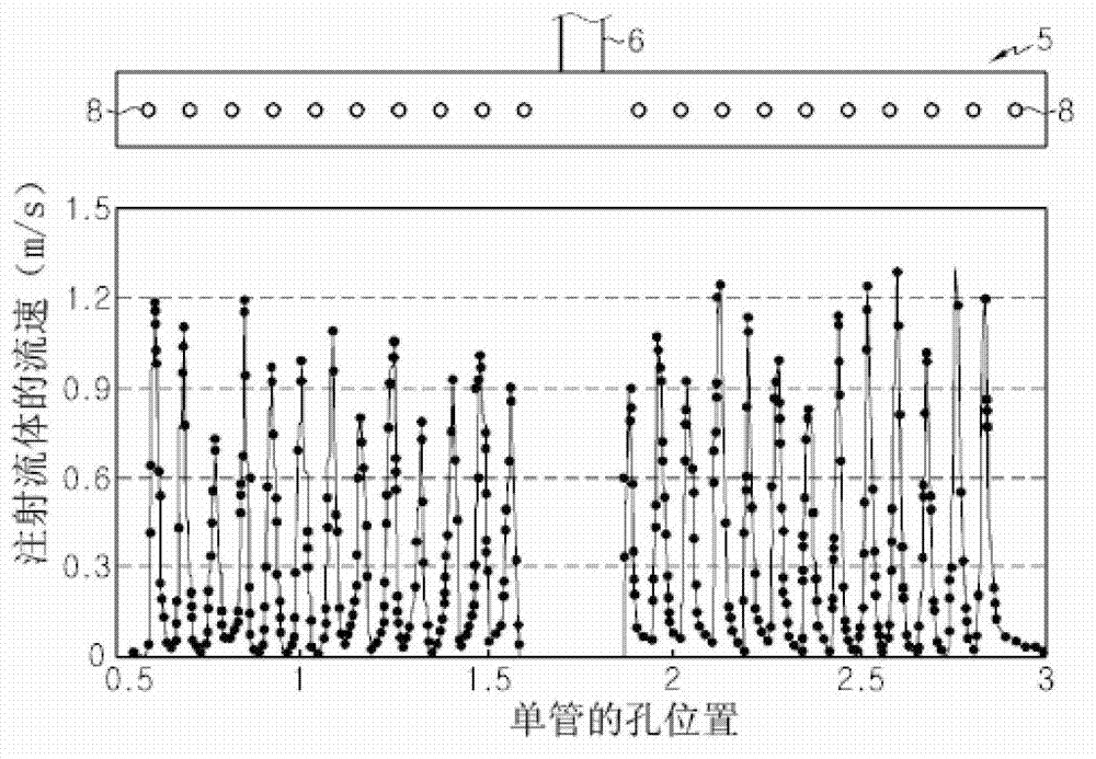
[0090] Figure 16 is a graph showing the flow rate test results of fluid released through each slit when the fluid supply devices according to the first, second and seventh embodiments are respectively applied to the membrane cleaning system according to the preferred embodiment of the present invention.

[0091] refer to Figure 16 , the double-tube type fluid supply device used in this experimental example has six slits (such as rear slits) continuously formed on one side of the outer tube along the length direction and six slits (such as front slits) continuously formed on the other side of the outer tube (such as front slit). Thus, in Figure 16 The Arabic numerals marked on the upper part close to the double pipe 300 represent the slit numbers (1-6) formed on the rear side and the slit numbers (7-12) formed on the front side respectively. Therefore, the measurements in this graph represent the flow rate of fluid injected through each slit.

[0092] according to Figu...

experiment example 1

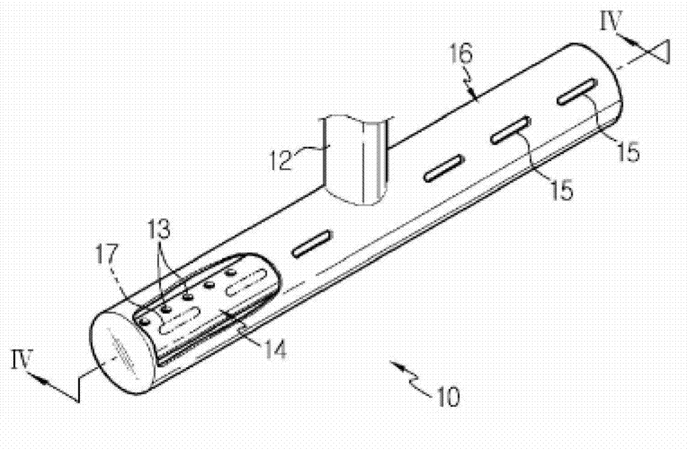
[0099]Table 2 shows the case of using the double tube type fluid supply device 10 according to the first embodiment of the present invention. In the double tube used in this Experimental Example 1, the inner tube 14 and the outer tube 16 each have a circular cross section. In other words, the inner tube 14 has a diameter of 100 mm, and each hole 13 has a diameter of 10 mm. Furthermore, the diameter of the outer tube 16 is 130 mm, and the length of the slits 15 and 17 is 240 mm.

[0100] Table 2

[0101]

experiment example 2

[0103] Table 3 shows the case of using the double tube type fluid supply device 20 according to the second embodiment of the present invention. In the double tube used in this Experimental Example 2, the inner tube 24 and the outer tube 26 each have an elliptical cross section. In other words, the inner tube 24 has a width of 200 mm and a height of 100 mm, and the hole 23 formed in the inner tube 24 has a diameter of 10 mm. Furthermore, the width of the outer tube 26 is 230 mm, the height is 130 mm, and the length of the slits 25 and 27 of the outer tube 26 is 240 mm.

[0104] table 3

[0105]


PUM


Abstract

The present invention relates to a fluid supply apparatus including: an inner tube in which a plurality of holes are arranged to distribute a fluid supplied from a supply unit and both ends of which are sealed to have a predetermined length; and an outer tube which is coaxially or non-coaxially arranged with respect to the inner tube and in which a plurality of slots are arranged to inject the fluid distributed to the inside through the holes to the outside and which have substantially the same length as the inner tube.

Description

[0001] Cross References to Related Applications [0002] This application claims priority from Korean Patent Application No. 10-2010-0080446 filed in Korea on Aug. 19, 2010, the entire contents of which are incorporated herein by reference. technical field [0003] The present invention relates to a fluid supply device and systems and methods for cleaning membranes using the device. More particularly, the present invention relates to a fluid supply device having an improved structure for uniformly and stably supplying cleaning fluid to clean a film (such as a film) stencil located in a tank storing the fluid, and to cleaning the film using the same systems and methods. Background technique [0004] For example, a system for producing a film or a roll-type plate (hereinafter referred to as "film") having a film-type sheet of several millimeters or tens of millimeters performs a cleaning process to remove impurities adhering to the surface of the roll-type film, The film or ...

Claims


Application Information

Patent Timeline
Patent Type & Authority Applications(China)
IPC IPC(8): B08B3/04B08B3/02
CPCB08B3/04B05C11/00G03D15/00B08B3/022B08B3/041B08B3/10
Inventor 徐英株郑在皓张道基廉基校林艺勳金哉旼闵庚勳朴元灿
Owner LG CHEM LTD
Why Eureka
Try Eureka