
Lighting device for airports

A technology for lighting devices and airports, which is applied to lighting devices, lighting auxiliary devices, components of lighting devices, etc., can solve the problems of installation trouble, and achieve the effect of reducing installation costs and improving maintenance convenience.

Inactive Publication Date: 2013-05-01
HELLA KG HUECK & CO
View PDF5 Cites 2 Cited by
  • Summary
  • Abstract
  • Description
  • Claims
  • Application Information

AI Technical Summary

Problems solved by technology

The disadvantage of this known lighting device is that it is relatively complex to install and that a number of different components are provided for heat dissipation

Method used


Image

  • Lighting device for airports
  • Lighting device for airports
  • Lighting device for airports

Examples


Embodiment Construction

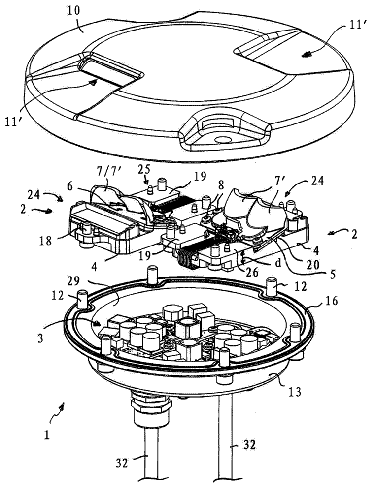
[0014] The lighting device according to the invention can preferably be used at airports as an underground signal light in order to mark roadways or taxiways.

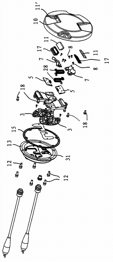
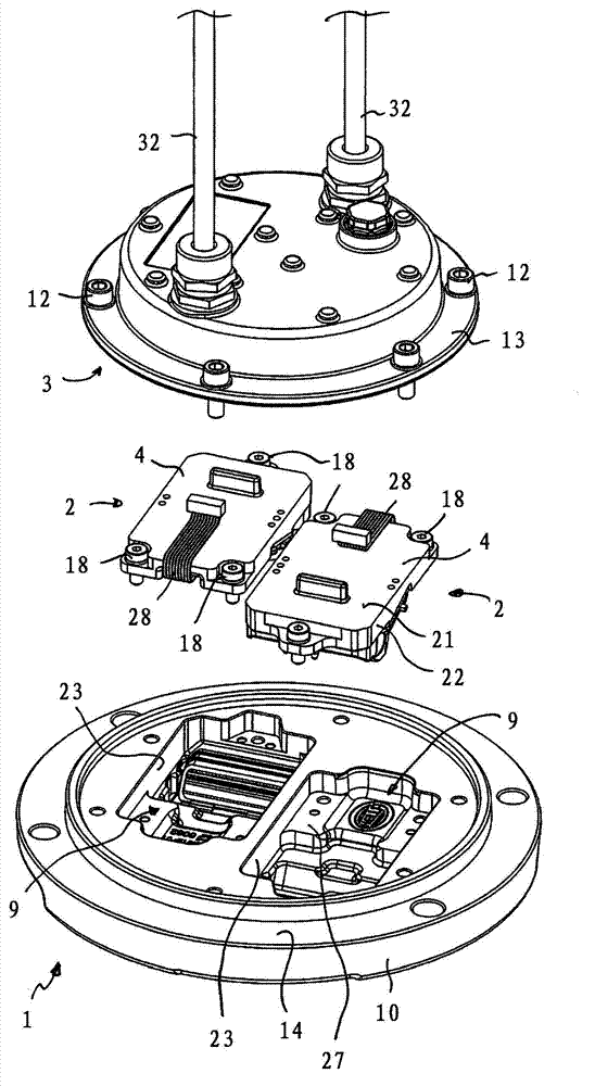
[0015] The lighting device comprises a housing 1 in which essentially two lighting modules 2 and a control electronics 3 are arranged.

[0016] The light emitting modules 2 respectively have a solid rectangular heat conduction block 4 , on which a light source seat 5 with a light source 6 and a reflector 7 are fixed through a bolt connection 8 . The light source holder 5 is designed as a printed circuit board on which LED light sources 6 , in the present case two LED light sources 6 (LED chips), are arranged. The reflective surfaces 7 ′ are respectively assigned to the LED light sources 6 , so that the light emitted by the light sources 6 can be deflected in the direction of the light panel 11 inserted in the recess 11 ′ of the housing upper part 10 and then radiate into the surroundings. The housing upper part 10 is ...


PUM


Abstract

The invention relates to a lighting device for airports, in particular flush lights, having a housing comprising a housing base (13) and a housing top (10), wherein the housing top comprises a recess for receiving a light disc (11, 11'), by means of which light from a light source disposed in the interior of the housing can be emitted to the surroundings, having a light source carrier (5) on which the light source is mounted, wherein the light source carrier is attached to a heat transfer block (4) locked in a recess of the housing top, wherein edges and / or at least partially flat sides of the heat transfer block directly contact the corresponding sides of the recess.

Description

technical field [0001] The present aspect relates to a lighting device for an airport, in particular an underground signal light, comprising: a housing with a housing lower part and a housing upper part, wherein the housing upper part has a recess for receiving a light panel, through which The light board, the light from the light source arranged in the inner cavity of the casing can be injected into the surrounding environment; the light source seat, the light source is installed on the light source seat. Background technique [0002] DE 20 2009 009 583 U1 discloses a lighting device for airports which, as an underground signal light, comprises a housing with a housing lower part and a housing upper part. In the housing, a light source is provided on the light source seat. The light panel is positioned in the recess of the upper part of the housing so that the light emitted from the light source can be emitted to the outside within a prescribed angle range. In order to di...

Claims


Application Information

Patent Timeline
Patent Type & Authority Applications(China)
IPC IPC(8): B64F1/20
CPCF21W2111/06F21V15/011F21V29/002F21V21/00F21V29/246F21V17/12F21V29/262F21V7/00F21Y2101/02F21V29/004B64F1/205F21V29/22F21V29/507F21V29/70F21V29/71F21V29/713F21V29/89F21Y2115/10B64F1/20F21V15/01
Inventor B·阿贝尔T·A·勒贝克R·吕特尔K·奥拉斯
Owner HELLA KG HUECK & CO
Learn More