
Method for controlling a turbomachine

A technology of turbine units and turbines, applied in the direction of controlling generators, control systems, mechanical equipment, etc., can solve problems such as high over-speed, shutdown of turbine units, etc., and achieve the effect of avoiding time delay

Active Publication Date: 2015-10-14
SIEMENS ENERGY GLOBAL GMBH CO & KG
View PDF7 Cites 0 Cited by
  • Summary
  • Abstract
  • Description
  • Claims
  • Application Information

AI Technical Summary

Problems solved by technology

The unloading of the electrical load shortly after the interruption of the short-circuit can in turn lead to very high overspeeds, which lead to a response of the associated protective device and thus to a shutdown of the turbomachine

Method used


Image

  • Method for controlling a turbomachine
  • Method for controlling a turbomachine
  • Method for controlling a turbomachine

Examples


Embodiment Construction

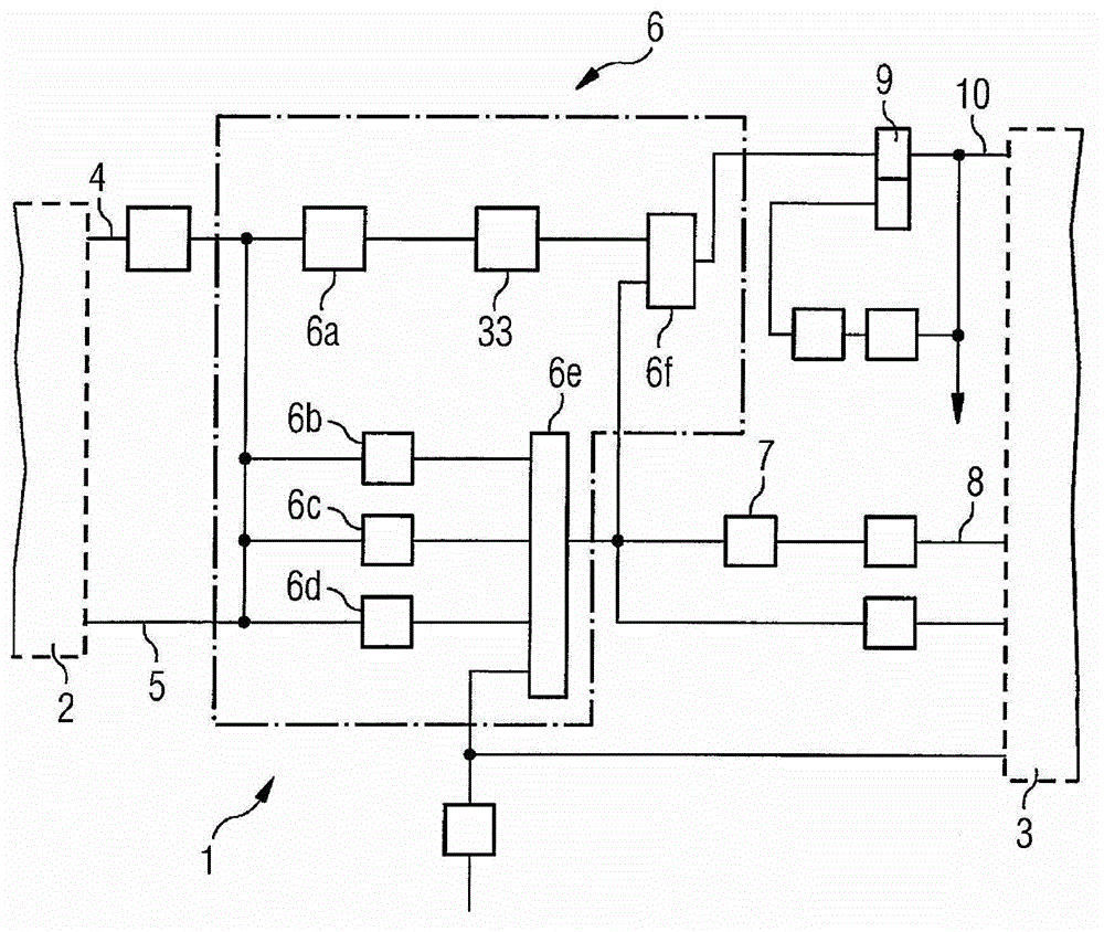
[0020] exist figure 1 A circuit arrangement or device 1 according to the invention for controlling a turbomachine, not shown further, with a generator 2 and a turbine 3 is shown in . The device 1 comprises as main elements a PEL signal line 4 and a PSW signal line 5 , which lead from the generator 2 to a mechanism 6 for providing a first signal. The mechanism 6 is designed as a control device in which a total of six switching elements 6 a , 6 b , 6 c , 6 d , 6 e and 6 f are formed. In this case, the actual power PEL of the generator 2 is transmitted via the PEL signal line 4 to the switching element 6 a, which checks whether the actual power PEL has dropped suddenly by a preset value GPLSP. In particular, a reduction in the form of a mutation of more than 70% was examined here. In order to check this power jump, the power signal PEL is first filtered by the DT1 module 33 .

[0021] In the switching element 6b it is deduced from the input signal PEL whether the actual power ...


PUM


Abstract

A signal indicating reduction in actual power of generator (2) is generated. A signal indicating short circuit interruption is reset, during predetermined time period and the signal is interrupted during another time period. A turbine (3) is braked and accelerated with respect to reset signal. A signal indicating load shedding of turbo generator is generated, when the difference between target power and actual power of generator is greater than specific value. An independent claim is included for device for controlling turbine generator.

Description

technical field [0001] The invention relates to a method for controlling a turbomachine. Background technique [0002] Turbosets used in particular in steam power plants already run at high rotational speeds during normal operation. In the event of a fault, this rotational speed can increase and, in unfavorable cases, lead to damage to the turbomachine. Therefore, the control strategy of the turbomachine must meet the highest demands. This control strategy is particularly relevant in the case of grid failures and rapid load changes. If, for example, the rotational speed of a generator belonging to a turbogroup deviates significantly from the nominal value and the associated shaft is at risk of slipping, the entire turbogroup must be specifically disconnected from the associated network and reduced to its own requirements, so-called unloading to its own requirements. demand. After said unloading, the power at the terminals of the generator drops to very small values ​​for...

Claims


Application Information

Patent Timeline
Patent Type & Authority Patents(China)
IPC IPC(8): F01K13/02F01D21/00H02P9/10H02P9/04
CPCF01K13/02H02P9/04H02P9/102
Inventor 马丁·本瑙尔黑里贝特·韦尔特斯
Owner SIEMENS ENERGY GLOBAL GMBH CO & KG
Learn More