Supercharge Your Innovation With Domain-Expert AI Agents!

Tire contour measurement data correction method and tire visual inspection device

一种外观检查装置、测量数据的技术,应用在测量装置、采用光学装置、仪器等方向

Inactive Publication Date: 2013-05-01
BRIDGESTONE CORP
View PDF7 Cites 10 Cited by
  • Summary
  • Abstract
  • Description
  • Claims
  • Application Information

AI Technical Summary

Problems solved by technology

[0013] The present invention has been made in consideration of the problems of the prior art described above, and aims at correcting the shape deformation due to deflection with respect to the tire shape measurement data, so that even for a deflected tire, it can be performed without preparatory work. Or perform visual inspection correctly without reducing productivity

Method used


Image

  • Tire contour measurement data correction method and tire visual inspection device
  • Tire contour measurement data correction method and tire visual inspection device
  • Tire contour measurement data correction method and tire visual inspection device

Examples


Embodiment Construction

[0029] Embodiments of the present invention will be described below by referring to the drawings.

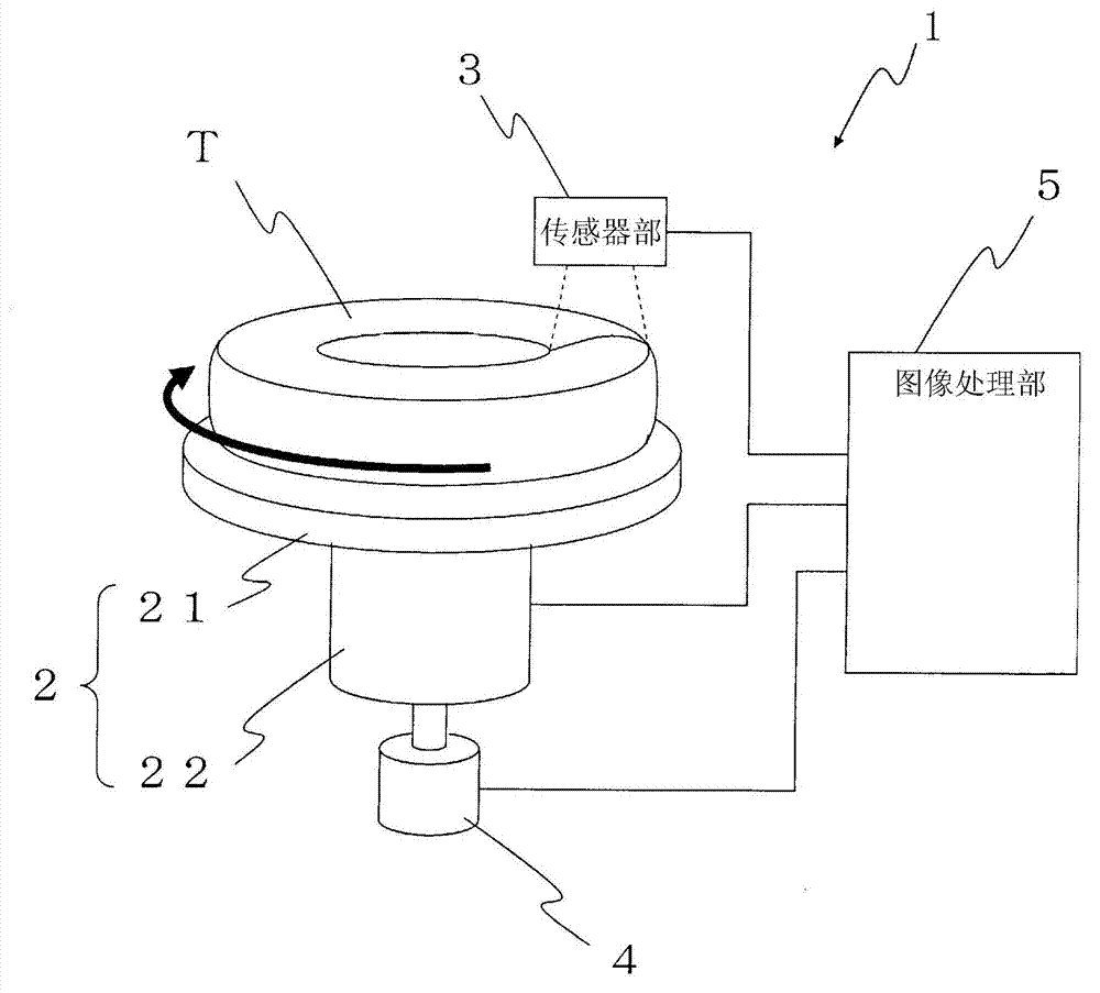
[0030] figure 1 is a block diagram showing the configuration of a tire appearance inspection device according to one embodiment of the present invention.

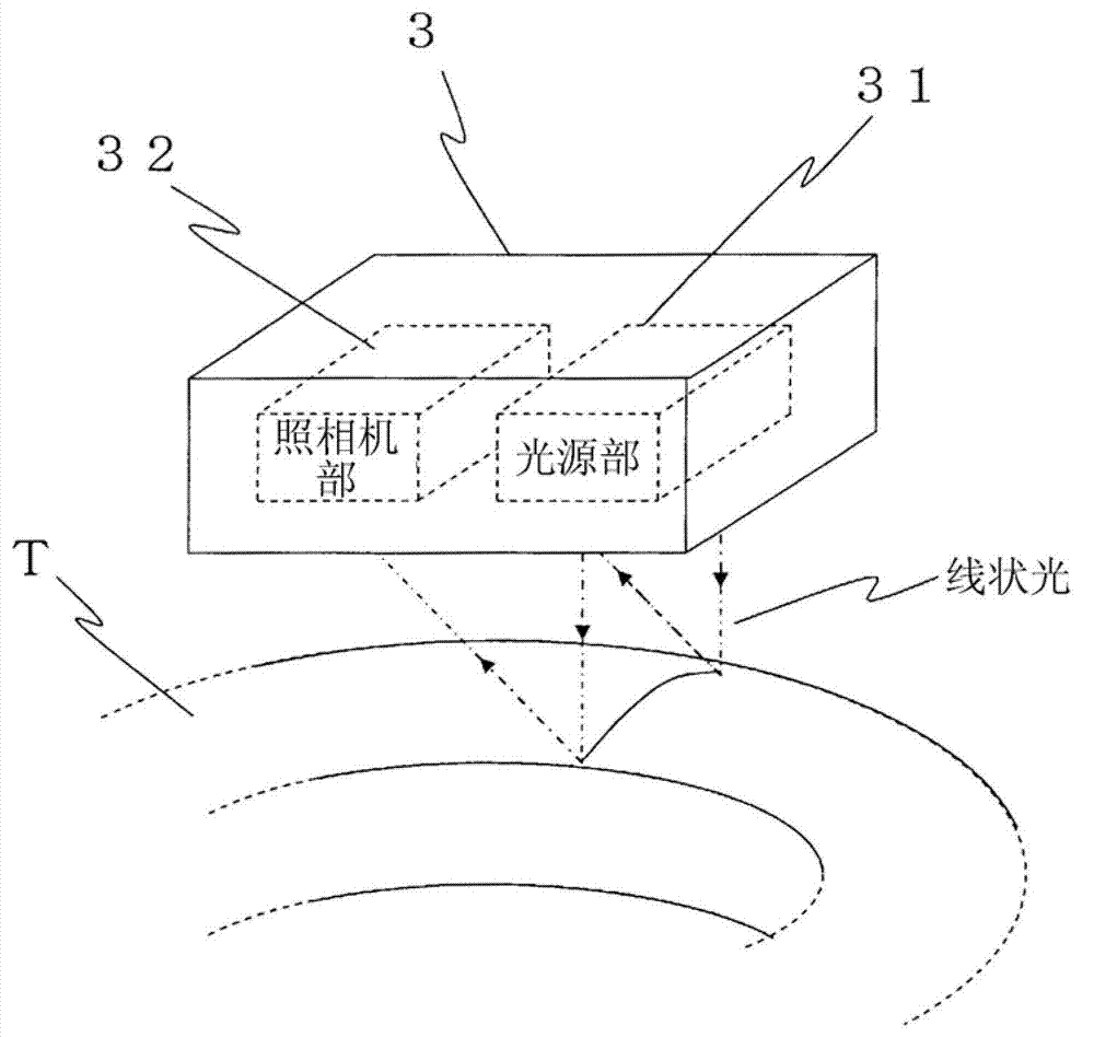
[0031] The tire appearance inspection device 1 has: a tire rotating unit 2 for rotating a tire T to be inspected by, for example, a stepping motor; a sensor unit 3 for irradiating the tire T with linear light and capturing an image of the linear light; The rotation angle detection unit 4 is used to detect the rotation angle of the tire rotation unit 2 ; and the image processing unit 5 is used to process the linear light image captured by the sensor unit 3 .

[0032] The tire rotating part 2 includes: a disc-shaped tire placing platform 21 for placing the tire T in a lateral direction; A stepping motor is built in to rotate and drive the tire placement table 21 .

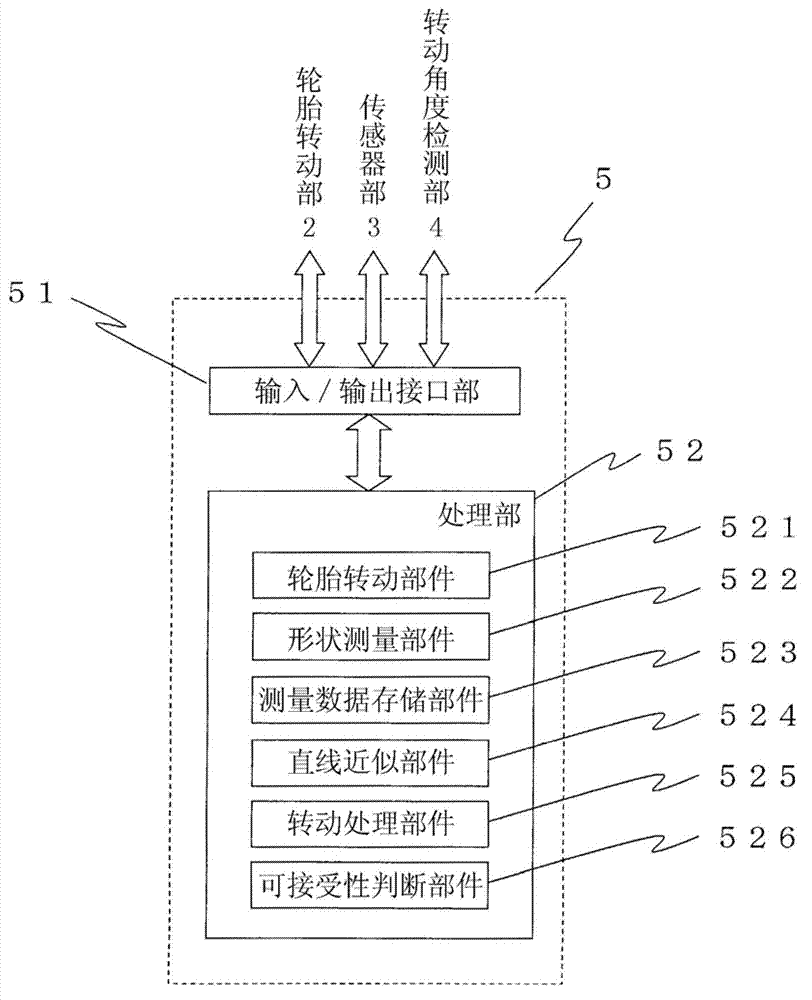
[0033] figure 2 It is a block diagram showing the config...


PUM


Abstract

The purpose of the invention is to perform correction of a contour deformation attributable to a tire deflection on tire contour measurement data in order to correctly perform a visual inspection on a tire having deflection. A tire contour measurement data correction method comprises steps of: acquiring, using a sensor unit (3), a sidewall image along a tire radial direction at predetermined rotation angle intervals while rotating a tire (T) to be inspected by a tire rotating unit (2); dividing the sidewall image by a predetermined ratio by an image processing unit (5) and approximating the sidewall image of each of the divided sections by a line; calculating the slope angle of the approximated line from a horizontal direction; and rotating the sidewall image of each of the divided sections so that the slope angle of the approximated line is matched with a predetermined angle specified for each of the divided sections.

Description

technical field [0001] The invention relates to a tire shape measurement data correction method and a tire appearance inspection device for judging whether the tire appearance is acceptable. Background technique [0002] When it is to be judged whether the shape of the tire is acceptable or not, the rubber material portion as the tire main body portion constituting the outer peripheral portion is attached to the ring-shaped metal member (rim) constituting the inner peripheral portion of the tire, and after filling the inside with air, grasps such as The appearance shape of the tire side (sidewall) and judge whether it is acceptable. [0003] As these methods for grasping the tire external shape, a method using a three-dimensional shape measurement method called an optical sectioning method (see Patent Document 1) and a method using an optical displacement sensor (see Patent Document 2) are known. [0004] Here, the light sectioning method is a method of irradiating the tire...

Claims


Application Information

Patent Timeline
Patent Type & Authority Applications(China)
IPC IPC(8): G01B11/24
CPCG01B11/25H04N7/18G01B21/04
Inventor 藤井知彦水谷彰伸
Owner BRIDGESTONE CORP
Features
  • R&D
  • Intellectual Property
  • Life Sciences
  • Materials
  • Tech Scout
  • Unparalleled Data Quality
  • Higher Quality Content
  • 60% Fewer Hallucinations
Learn More