Automatic assembly mechanism for steel ball

An automatic assembly and steel ball technology, which is applied in the direction of assembly machines, metal processing equipment, manufacturing tools, etc., can solve problems such as inability to adapt to sliding balance, product flow of leaking balls, and inability to meet the increase in bearing capacity.

Active Publication Date: 2013-05-08
KERUI AUTOMATION TECH SUZHOU
View PDF6 Cites 9 Cited by
  • Summary
  • Abstract
  • Description
  • Claims
  • Application Information

AI Technical Summary

Problems solved by technology

[0003] With the continuous updating of products, the previous one-sided volleyball slide rail can no longer meet the demand, not only can not meet the demand for increased bearing capacity, but also can not adapt to the balance of sliding
[0004] At present, the slide rail of the new product four-row steel ball cannot be realized by the old production method, and the assembly cannot be realized by hand, nor can it be realized by a semi-automatic method.
At the same time, to ensure the consistency of the product and the appropriate sliding force, it is necessary to cooperate well with the ball. Whether there is a leakage of the ball cannot be found during production and inspection, so that products with leakage of the ball often flow into the production line

Method used


Image

  • Automatic assembly mechanism for steel ball
  • Automatic assembly mechanism for steel ball

Examples


Embodiment Construction

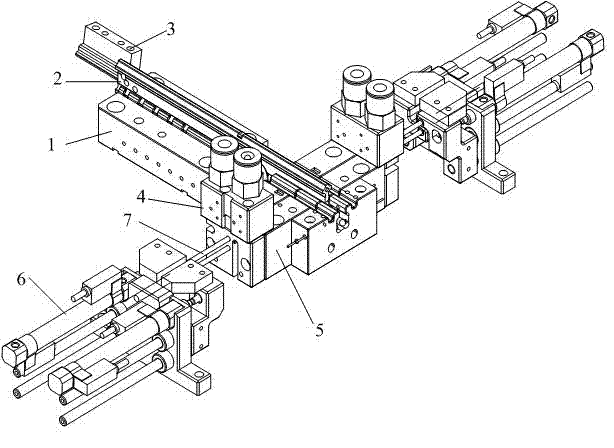
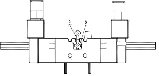
[0017] Such as figure 1 As shown, the steel ball automatic assembly mechanism includes a steel ball cage 2, a scoring mechanism, a ball pushing mechanism, a channel fixture 1 and a ballway fixture 5. The steel ball cage 2 has four corners distributed in a square shape, and each Each corner is provided with a notch groove for accommodating steel balls, the steel ball cage 2 is placed in the chute of the channel fixture 1, and the rear end of the steel ball cage 2 is provided with a pusher block 3, which is connected with the pusher mechanism Connected, the front end of the channel jig 1 is docked with the fairway jig 5, and the fairway jig 5 is provided with a chute for the steel ball cage to slide, and the left and right sides of the fairway jig chute are respectively arranged on the two fairway , the four lanes coincide with the notch grooves of the steel ball cage, and the left and right parts of the lane jig 5 are respectively equipped with a goal mechanism, and an optical ...


PUM


Abstract

The invention relates to an automatic assembly mechanism for a steel ball. The automatic assembly mechanism for the steel ball comprises a steel ball retainer, ball feeding mechanisms and ball pushing mechanisms. Notch grooves for containing the steel balls are arranged at four corners of the steel ball retainer. The steel ball retainer is placed in a sliding groove of a channel jig. A material pushing block is arranged at the back end of the steel ball retainer. The material pushing block is connected with a material pushing mechanism. The front end of the channel jig is in a butt joint with a ball channel jig, wherein a sliding groove which the steel ball retainer can slide in is arranged in the ball channel jig. Two ball channels are arranged at the left side and the right side of the sliding groove of the ball channel jig, wherein the four ball channels are respectively matched with the notch grooves of the steel ball retainer. The ball feeding mechanisms are respectively installed on the left portion and the right portion of the ball channel jig. Two ball feeding channels of the left ball feeding mechanism are communicated with the left ball channels of the ball channel jig, and the two ball feeding channels of the right ball feeding mechanism are communicated with the right ball channels of the ball channel jig. The ball pushing mechanisms are respectively arranged on the left side and the right side of the ball channel jig. Pushing rods of the ball pushing mechanisms stretch into the ball channels of the ball channel jig. The problems that the four rows of ball sliding rails are difficult to assemble and the ball loss can not be detected are resolved.

Description

technical field [0001] The invention relates to an automatic assembly mechanism for steel balls, which is used for automatic assembly of steel balls in steel ball guide rails. Background technique [0002] The steel ball is one of the core parts of the rolling unit of the guide rail. The accuracy of the assembly and the precision of the grease directly affect the push-pull force and the uniformity of the bearing of the guide rail. [0003] With the continuous updating of products, the previous one-sided volleyball slide rail can no longer meet the demand, not only can not meet the demand for increased bearing capacity, but also can not adapt to the balance of sliding. [0004] At present, the slide rail of the new product four-row steel ball cannot be realized by the old production method, and the assembly cannot be realized by hand, nor can it be realized by a semi-automatic method. At the same time, to ensure the consistency of the product and the appropriate sliding forc...

Claims


Application Information

Patent Timeline
Patent Type & Authority Applications(China)
IPC IPC(8): B23P21/00
Inventor 刘国发
Owner KERUI AUTOMATION TECH SUZHOU
Why Eureka
Try Eureka