Tool for mounting ejector-body

A technology of cylinders and tools, which is applied in the field of tools for installing tappets, and can solve problems such as difficulty in installing tappets into the installation holes of cylinder blocks, easy slipping of tappets and tappets, troubles in installing tappets, etc. Achieve the effects of eliminating hidden dangers in production safety, solving assembly difficulties, and simple structure

Active Publication Date: 2016-11-23
GUANGXI YUCHAI MASCH CO LTD
View PDF8 Cites 4 Cited by
  • Summary
  • Abstract
  • Description
  • Claims
  • Application Information

AI Technical Summary

Problems solved by technology

The existing method is generally to directly take the outer surface of the tappet manually by hand, and manually move it to the tappet installation hole of the cylinder block for assembly. However, before the tappet is assembled, the inside and outside of the entire tappet The surface is filled with lubricating oil, causing workers to be unstable or the tappet is easy to slip off the hand and damage the tappet, and it is also difficult to install the tappet into the mounting hole of the cylinder block
At the same time, after the tappet body is loaded into the cylinder block mounting hole, it is necessary to require the middle hole to be aligned with the rib hole on the cylinder block, so that the tappet body is fixed with screws through the rib hole, because the tappet body is loaded into the cylinder block mounting hole Finally, there are ribs near its periphery, and the installation tools can only be taken out from the top of the tappet body, which has strict requirements on the installation tools, so it has caused great trouble to the installation of the tappet body

Method used


Image

  • Tool for mounting ejector-body
  • Tool for mounting ejector-body
  • Tool for mounting ejector-body

Examples


Embodiment Construction

[0019] The present invention will be further described below in conjunction with the specific embodiments in the accompanying drawings.

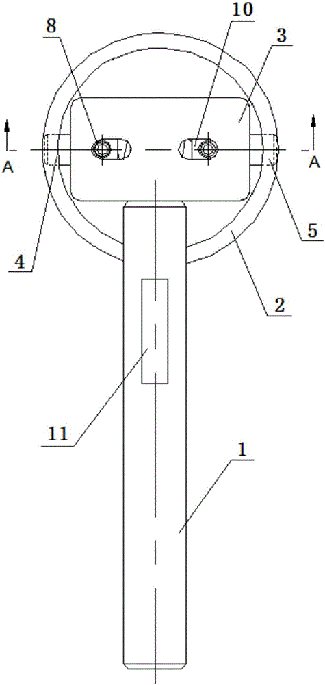
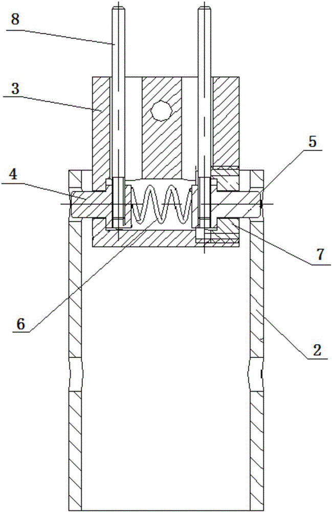
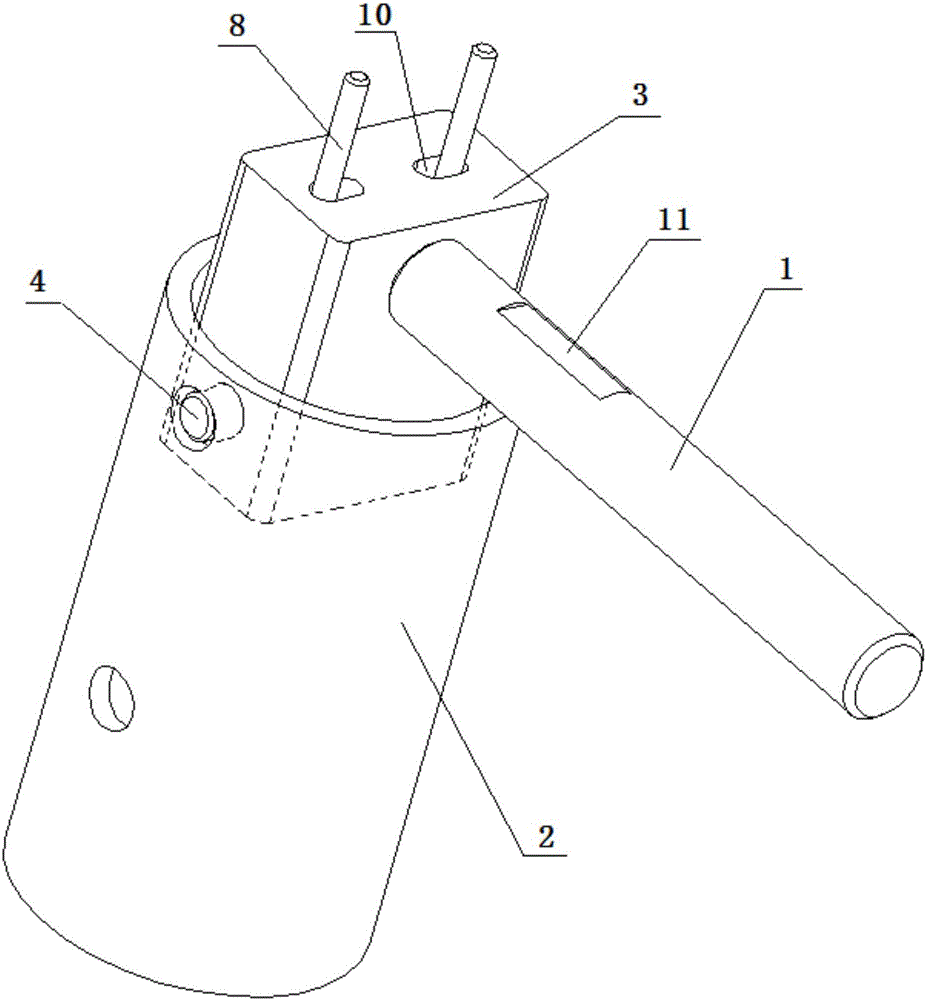
[0020] refer to Figure 1-5 , a tool for installing a tappet body of the present invention includes a handle 1, and one end of the handle 1 is provided with a push rod seat 3 that can be movably inserted into the inner cavity of the tappet body 2, and the handle 1 is perpendicular to the push rod seat 3 , the end of the handle 1 connected with the push rod base 3 is provided with an external thread, and at the same time, a screw hole matching the external thread on the handle 1 is provided on the push rod base 3, and the handle 1 can be fixed by threaded connection On the push rod base 3, it is convenient to assemble the handle 1 and the push rod base 3, and a groove 11 for taking the handle 1 is provided on the side of the handle 1 close to the push rod base 3, which is convenient for workers to operate; Both sides of the push rod seat 3 b...


PUM


Abstract

The invention discloses a tool for mounting an ejector-body. The tool comprises a handle, wherein a push rod seat which is movably inserted into an inner cavity of the ejector-body is arranged at one end of the handle; a first ejector block and a second ejector block which can move back and forth and are adaptive to the size of an inner hole on the side wall of the ejector-body are arranged on two sides of the push rod seat below the handle; a compression spring is arranged between the first ejector block and the second ejector block; a plug screw which jointly lock the first ejector block, the compression spring and the second ejector block is arranged on the push rod seat located on one side of the second ejector block; and push rods which are connected to the first ejector block and the second ejector block and perpendicularly protrude out of the top of the push rod seat for controlling the first ejector block and the second ejector block to move back and forth are arranged on the first ejector block and the second ejector block, respectively. The tool disclosed by the invention is simple in structure. By designing the push rod seat, which can be inserted into the inner cavity of the ejector-body, with stretchable ejector blocks, the ejector-body is quickly, simply and conveniently mounted by locating by virtue of the ejector blocks and the inner hole on the side of the ejector-body.

Description

technical field [0001] The invention relates to the technical field of engine assembly, more specifically, it relates to a tool for installing tappets. Background technique [0002] The tappet body is an important part of the engine. During the assembly process of the engine, the tappet body is assembled. The existing method is generally to directly take the outer surface of the tappet manually by hand, and manually move it to the tappet installation hole of the cylinder block for assembly. However, before the tappet is assembled, the inside and outside of the entire tappet The surfaces are all filled with lubricating oil, which causes the workers to hold the tappet or the tappet easily slips off the hand and damage the tappet, and it is also difficult to pack the tappet into the cylinder block mounting hole. At the same time, after the tappet body is loaded into the cylinder block mounting hole, the middle hole needs to be aligned with the rib hole on the cylinder block, s...

Claims


Application Information

Patent Timeline
Patent Type & Authority Applications(China)
IPC IPC(8): B25B27/00
CPCB25B27/00B25B27/14
Inventor 陶华江白小飞包世荣叶泽刚唐尤模符翠灵莫付军蒋易强李宗真陈朝辉
Owner GUANGXI YUCHAI MASCH CO LTD
Why Eureka
Try Eureka