Pneumatically actuated liquid dispensing valve and method

A technology for dispensing valves, liquids, used in the direction of liquid injection devices, devices for applying liquid to surfaces, valve details

Inactive Publication Date: 2013-05-08
NORDSON CORP
View PDF5 Cites 9 Cited by
  • Summary
  • Abstract
  • Description
  • Claims
  • Application Information

AI Technical Summary

Problems solved by technology

This also adversely affects the performance of the valve

Method used


Image

  • Pneumatically actuated liquid dispensing valve and method
  • Pneumatically actuated liquid dispensing valve and method
  • Pneumatically actuated liquid dispensing valve and method

Examples


Embodiment Construction

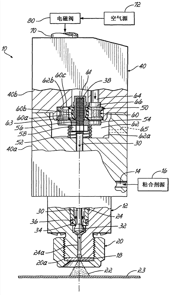
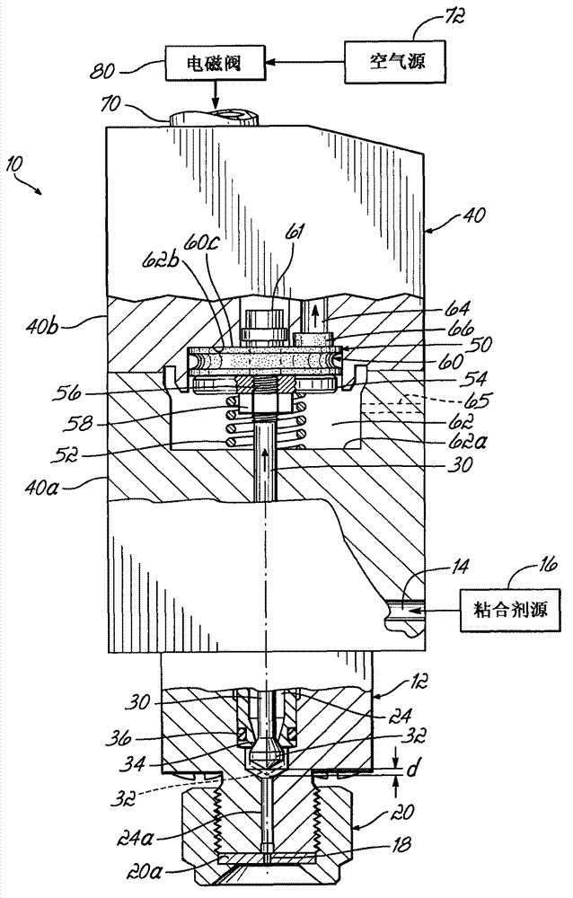
[0017] figure 1 and figure 2 A first embodiment of a liquid dispensing valve 10 is shown. Valve 10 includes a liquid dispensing portion 12 having a liquid inlet 14 for receiving liquid, such as a hot melt adhesive, from a pressurized source 16 . The liquid dispensing portion 12 also includes a liquid outlet 18 associated with the insert 20a of the nozzle 20 to discharge the liquid 22 onto the substrate 23 . It will be appreciated that the nozzle 20 is shown schematically and may have a variety of different forms and discharge liquid in a variety of ways. When dispensing liquid hot melt adhesive, for example, a swirl pattern, bead pattern, dot or other spray pattern may be expelled. A liquid passage 24 communicates between the liquid inlet 14 and the liquid outlet 18 . The valve member 30 is mounted to move relative to the liquid outlet 18 between an open position and a closed position, respectively at figure 1 and figure 2 shown in . More specifically, the valve membe...


PUM


Abstract

The invention provides a pneumatically actuated liquid dispensing valve and a method. The liquid dispensing valve includes a liquid dispensing portion with a liquid inlet, a liquid outlet), and a liquid passage communicating between the liquid inlet and liquid outlet. A valve member is mounted for movement relative to the liquid outlet between open and closed positions. An actuation portion is coupled with the liquid dispensing portion and includes an inflatable bladder structure. The inflatable bladder structure includes an interior adapted to be coupled in fluid communication with a source of positively pressurized air. The bladder structure (50) may be expanded by the positively pressurized air to move the valve member to at least one of the open or closed positions from the other of the open or closed positions. Methods of dispensing liquid, such as hot melt adhesive, from the valve are also disclosed.

Description

technical field [0001] The present invention relates generally to pneumatic liquid dispensing valves, such as those designed for dispensing liquid hot melt adhesives. Background technique [0002] Pneumatic liquid dispensing valves typically utilize a liquid dispensing section comprising: a liquid inlet for receiving a liquid such as a hot melt adhesive; Various forms discharge liquids in the form of sprays. The dispensing valve also includes a valve member, such as a valve stem or needle mounted for reciprocating movement between an open position and a closed position. The actuation portion includes a pneumatic actuator such as a piston coupled for movement with the valve stem. A piston is located within the piston chamber and a dynamic seal is located between the piston chamber and the liquid dispensing portion to prevent leakage of liquid into the piston chamber or pressurized air from the piston chamber into the liquid dispensing portion. The valve stem extends throug...

Claims


Application Information

Patent Timeline
Patent Type & Authority Applications(China)
IPC IPC(8): F16K31/12
CPCF16K31/126B05C11/10F16K31/1268B05C5/0237B05B1/30B05B9/01F16K31/1262B05B7/12B05B1/3013F16K31/128
Inventor 乔尔·E·赛内
Owner NORDSON CORP
Why Eureka
Try Eureka