Smart card connecting circuit for electronic equipment and electronic equipment

A technology for connecting circuits and electronic equipment, applied in the field of electronic information, can solve problems such as SIM card burnout, and achieve the effect of solving burnout and avoiding burnout

Active Publication Date: 2013-05-08
HUAWEI DEVICE CO LTD
View PDF4 Cites 19 Cited by
  • Summary
  • Abstract
  • Description
  • Claims
  • Application Information

AI Technical Summary

Problems solved by technology

[0004] The embodiment of the present invention provides a smart card connection circuit of an electronic device and an electronic device equipped with the smart card connection circuit, which solves the technical problem in the prior art that the SIM card is easily burned out when detached from the card holder

Method used


Image

  • Smart card connecting circuit for electronic equipment and electronic equipment
  • Smart card connecting circuit for electronic equipment and electronic equipment
  • Smart card connecting circuit for electronic equipment and electronic equipment

Examples


Embodiment 1

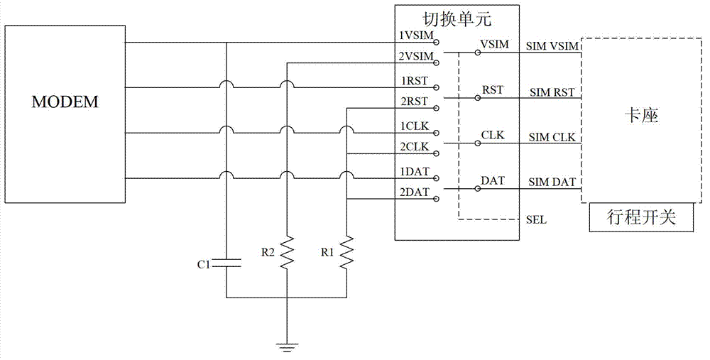
[0032] Such as figure 1 As shown, the smart card connection circuit for electronic equipment provided by the embodiment of the present invention can be applied to electronic equipment such as mobile phones and tablet computers (pads). This embodiment uses a SIM card in a mobile phone as an example for illustration. The SIM card connection circuit includes a card holder, a travel switch and a switching unit. The switching unit is equivalent to four synchronous single-pole double-throw switches. The right side is the input terminal, and the left side is two output terminals. The first output terminal is the modem (MODEM) of the mobile phone, and the second output terminal is the ground terminal.

[0033] The power line pin VSIM and each signal line pin (including reset signal line pin RST, clock signal line pin CLK, and data line pin DAT) on the deck are connected to each corresponding interface of the input end of the switching unit; travel switch The contacts of the travel sw...

Embodiment 2

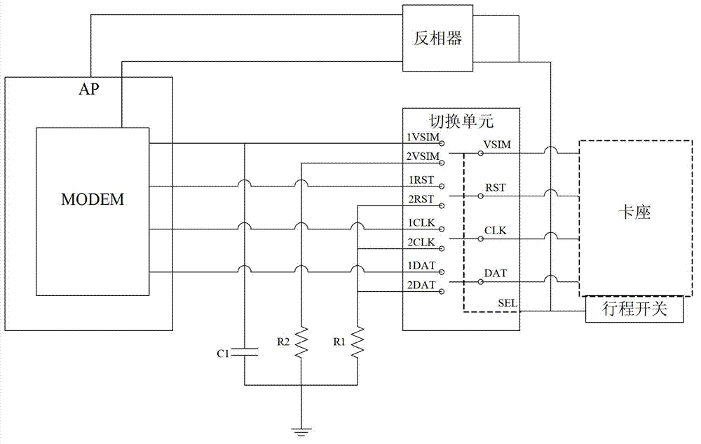
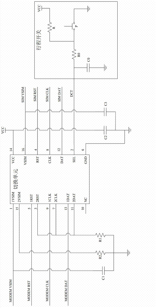
[0043] Such as figure 2 and image 3 As shown, in this embodiment, on the basis of Embodiment 1, the output end of the travel switch is also connected to the general purpose input / output (General Purpose Input Output, GPIO) interface of the MODEM, so that the MODEM can judge whether the SIM card is in place (card seat preset position).

[0044] Further, the output end of the limit switch is also connected to the GPIO interface of the application processor (application processor, AP) of the mobile phone, so that the AP can determine whether the SIM card is in place.

[0045] In addition, the correct sequence of powering on the SIM card is that the power line VSIM is powered on first, and the signal lines CLK, RST, and DAT are powered on last. When the SIM card is installed on the deck and is in the preset position, the SIM card touches the contact of the limit switch, and the AP of the mobile phone can detect that the SIM card is in place through the GPIO interface, so the A...

Embodiment 3

[0054] Such as Figure 4 As shown, on the other hand, the present invention also provides an electronic device, which is provided with any smart card connection circuit in Embodiment 1 and Embodiment 2 above. Specifically, the electronic device may be a mobile phone (mobile phone), and the smart card is used to connect the circuit to prevent the SIM card in the mobile phone from being burned when it is detached from the card holder.

[0055] Such as Figure 4 As shown, the card socket in the mobile phone is used to install the SIM card, and each contact on the SIM card is connected to the switching unit through the card socket, and further connected to the MODEM through the first output end of the switching unit. When the SIM card leaves the preset position on the card holder, the travel switch controls the switching unit to switch to the second output terminal, and each signal line pin on the card holder is first grounded through the switching unit, and then the power line p...


PUM


Abstract

The invention discloses a smart card connecting circuit for electronic equipment and the electronic equipment. The smart card connecting circuit for the electronic equipment and the electronic equipment belong to the technical field of electronic information and solves the technical problem in the prior art that a subscriber identity module (SIM) card is prone to be burned when separated from a card seat. The smart card connecting circuit comprises the card seat, a travel switch and a switch unit, wherein power line pins and each signal line pin on the card seat are connected with each corresponding connectors of the input end of the switch unit, the contacting point of the travel switch is arranged in the card seat, and the output end of the travel switch is connected with a control end of the switch unit. When the smart card on the preset position in the card seat leaves the preset position, the smart card leaves the contacting point of the travel switch, the travel switch controls the switch unit to switch to a second output end, each signal line pin on the card seat is connected with the ground through the switch unit first, and the power line of the card seat is connected with the ground through the switch unit after being leaded. The smart card connecting circuit for the electronic equipment and the electronic equipment are applicable to the electronic equipment including mobile phones, tablet personal computers and the like.

Description

technical field [0001] The invention belongs to the technical field of electronic information, and in particular relates to a smart card connection circuit of electronic equipment and electronic equipment provided with the smart card connection circuit. Background technique [0002] With the continuous development of electronic technology, electronic devices such as mobile phones and tablet computers have become common communication tools in people's daily life. Taking a mobile phone as an example, a Subscriber Identity Module (SIM) card is an important part of the mobile phone and is installed in a card holder in the mobile phone. The SIM card is provided with contacts for connecting power lines, ground wires, and various signal lines. When the SIM card is installed on the card holder, these contacts will be electrically connected to the corresponding pins on the card holder, and further through the card holder. Connect to the modem (MODEM) of the mobile phone. [0003] T...

Claims


Application Information

Patent Timeline
Patent Type & Authority Applications(China)
IPC IPC(8): H01R13/703H01R12/71
CPCH04M1/02H04B1/38G06F1/16G06K7/0069G06F13/4068H01R13/703
Inventor 唐科狄胡林彭忠辉
Owner HUAWEI DEVICE CO LTD
Why Eureka
Try Eureka