Micro radio frequency connector

A radio frequency connector, micro technology, applied in the direction of connection, two-part connection device, contact parts, etc., can solve the problem of unstable connection performance, and achieve the effect of enhancing electrical connection

Inactive Publication Date: 2013-05-08
FOXCONN (KUNSHAN) COMPUTER CONNECTOR CO LTD +1
View PDF2 Cites 0 Cited by
  • Summary
  • Abstract
  • Description
  • Claims
  • Application Information

AI Technical Summary

Problems solved by technology

[0003] Therefore, in view of the deficiencies of the aforementioned micro-RF connectors, it is necessary to design a new micro-RF connector to solve the problem of unstable electrical connection performance

Method used


Image

  • Micro radio frequency connector
  • Micro radio frequency connector
  • Micro radio frequency connector

Examples


Embodiment Construction

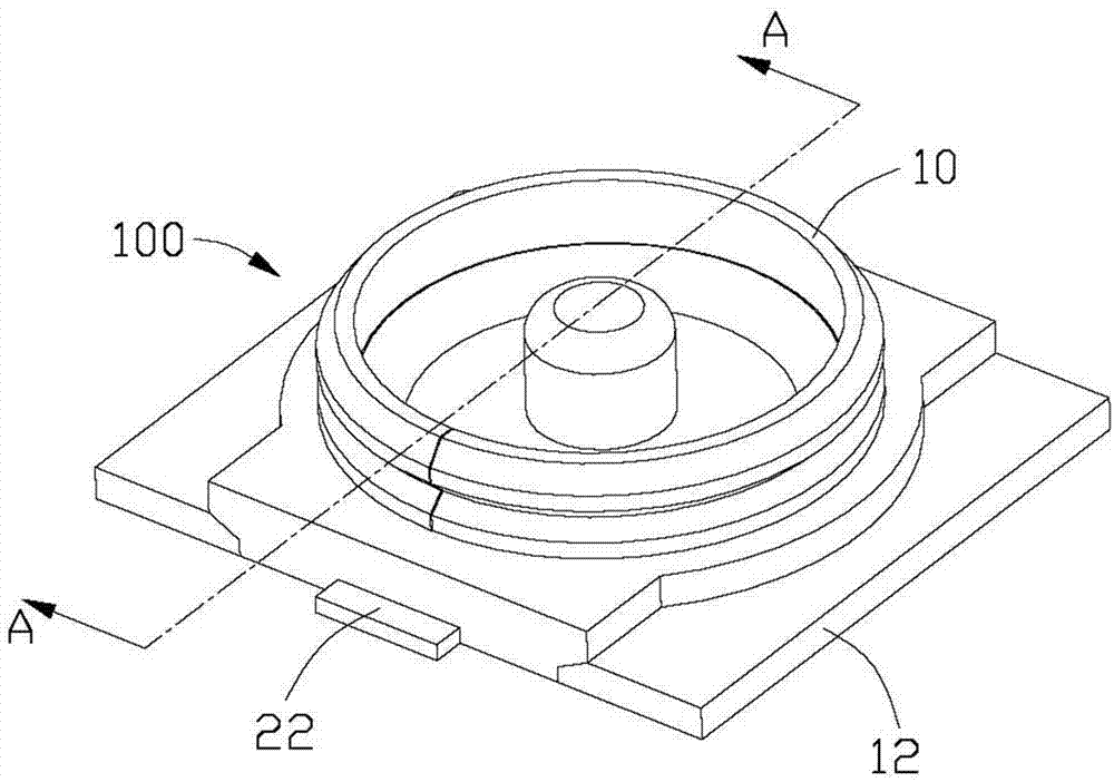
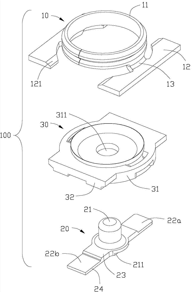
[0010] Such as figure 1 and figure 2 As shown, the present invention discloses a miniature radio frequency connector 100, which includes an outer conductor 10, a central conductor 20, and an insulator 30 for maintaining the outer conductor and the central conductor.

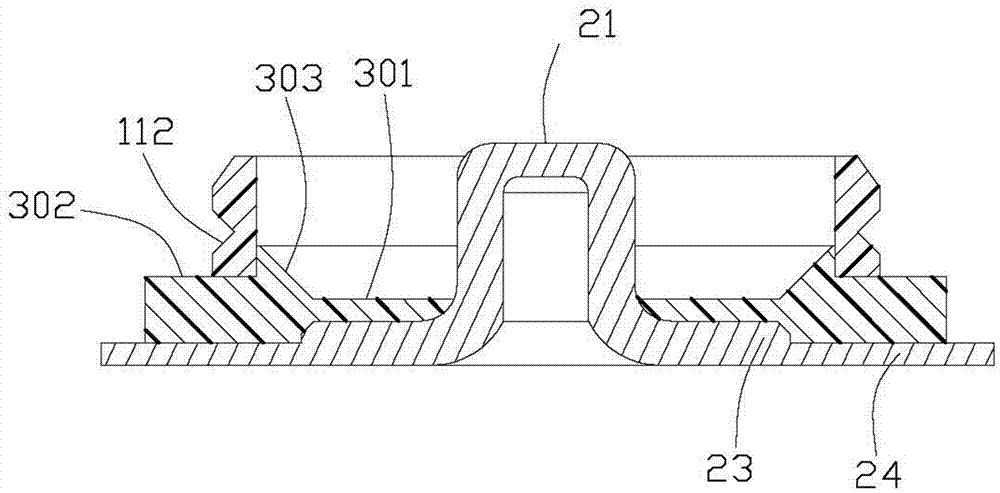
[0011] The outer conductor 10 includes a cylindrical portion and a pair of fixing portions 12 extending from the cylindrical portion 11 , the extending direction of which is perpendicular to the extending direction of the cylindrical portion. The cylindrical part 11 and the fixed part 12 are connected by a pair of connecting parts 13, and the inner surface 121 of the fixed part 12 is inclined. The central conductor 20 is formed by drawing, and has a contact part 21 located in the center of the cylindrical part and a pair of extension parts 22 (including 22a, 22b) extending from the contact part. The extension direction of the extension part 22 is perpendicular to the extension direction of the contact part. Th...


PUM


Abstract

A micro radio frequency connector comprises an outer conductor with a tubular part, a central conductor which is located on a contact part in the center of the tubular part and an insulator which is provided with a maintaining part used for maintaining the outer conductor and the central conductor. The micro radio frequency connector is characterized in that the central conductor is provided with extension parts which extend from two sides of the contact part, and the two extension parts at least extend to the outside of the tubular part. The two extension parts are capable of guaranteeing that the central conductor maintains on the insulator reliably and enhancing the electric connection at the same time.

Description

【Technical field】 [0001] The invention relates to a radio frequency connector, in particular to a miniature radio frequency connector. 【Background technique】 [0002] Chinese Patent Announcement No. CN102017331 patent discloses a miniature radio frequency connector, which includes: an outer conductor with a cylindrical portion; a central conductor with an axially extending contact portion in the inner space of the cylindrical portion; The insulator holds the conductor and the center conductor, and the center conductor has a holding portion and a welding portion extending along one side of the contact portion. As known in the industry, the size of micro RF connectors is very small, and the common size is as small as one-tenth of the nail cover. In such a thin condition, the existing products not only have poor welding effect, but also have low strength. Especially when docking, the center conductor is easily knocked and twisted, which affects the electrical connection. [0...

Claims


Application Information

Patent Timeline
IPC IPC(8): H01R24/40H01R13/02
Inventor 陈德金
Owner FOXCONN (KUNSHAN) COMPUTER CONNECTOR CO LTD
Why Eureka
Try Eureka