Low impedance, high bandwidth disk drive suspension circuit
- Summary
- Abstract
- Description
- Claims
- Application Information
AI Technical Summary
Benefits of technology
Problems solved by technology
Method used
Image

Examples
first embodiment
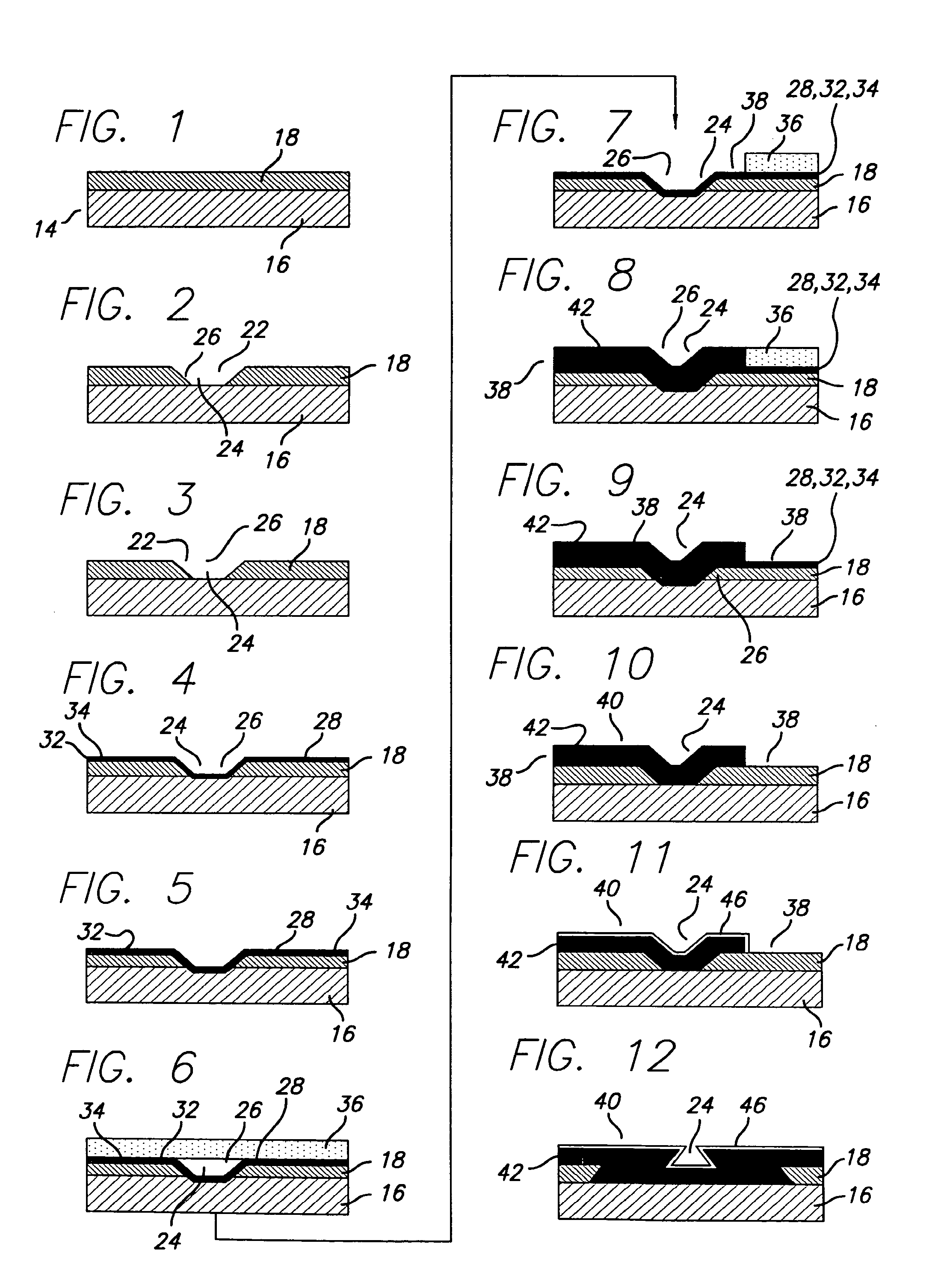
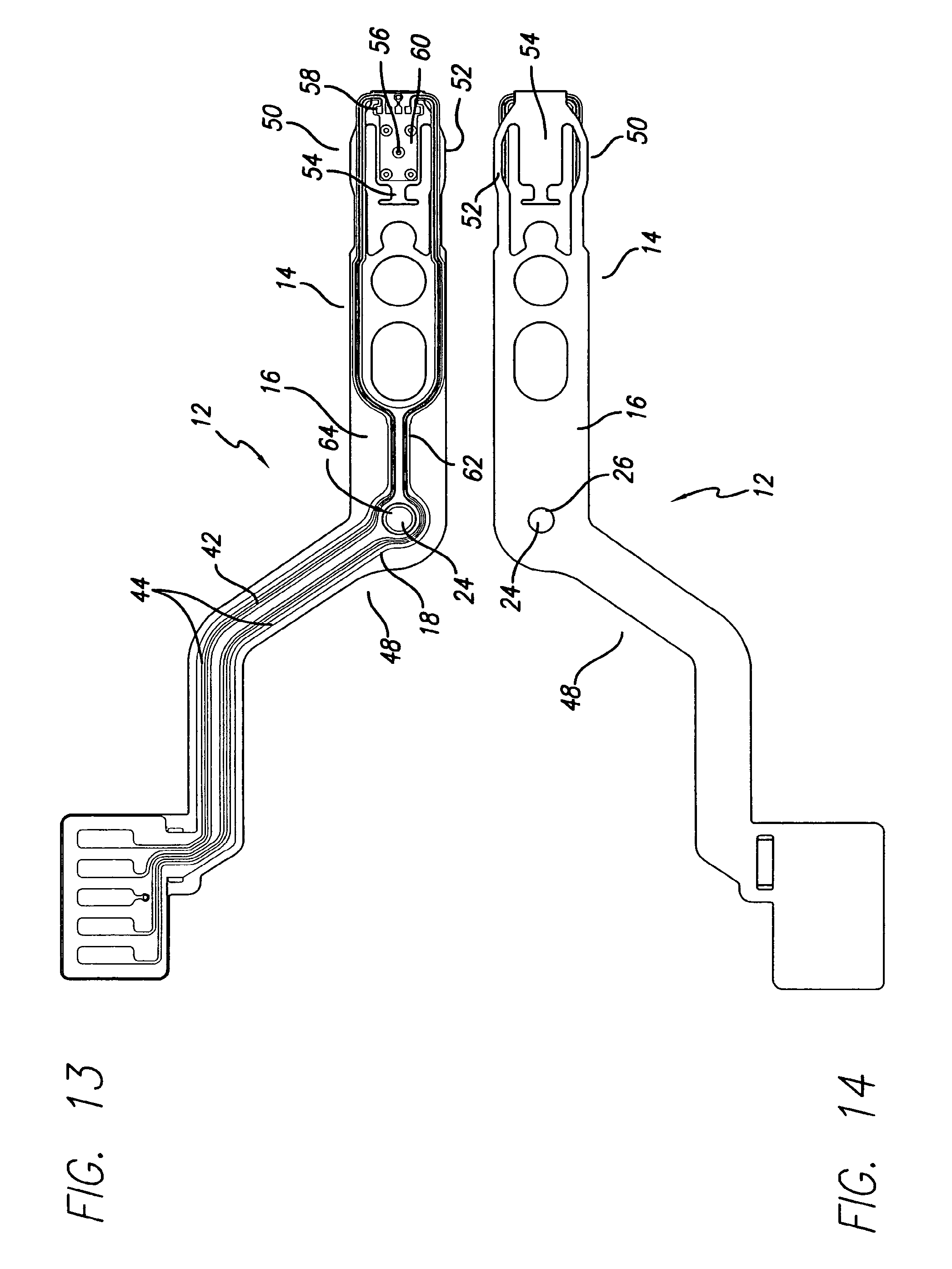
[0129]FIG. 46 is a top plan conceptual view of a reduced impedance suspension circuit having crossing signals according to a reduced impedance, reduced crosstalk suspension. FIG. 47 is a cross sectional view of the suspension circuit of FIG. 46 taken along section line 47-47. FIG. 46 is a conceptual plan view in the sense that it mainly shows the electrical paths without regard to certain other features.
[0130]In this embodiment, made by an additive circuit process, the suspension circuit includes a suspension substrate 416, preferably being a spring metal such as stainless steel or copper metallized stainless steel. Insulative layer 418 is a dielectric material, typically an organic polymer such as polyimide. On top of insulative layer 418 are deposited the signal conductors, typically made of pure copper or a high copper alloy. The signal conductors in this embodiment include first signal conductor 440, second signal conductor 450, third signal conductor 460, and fourth signal cond...
second embodiment
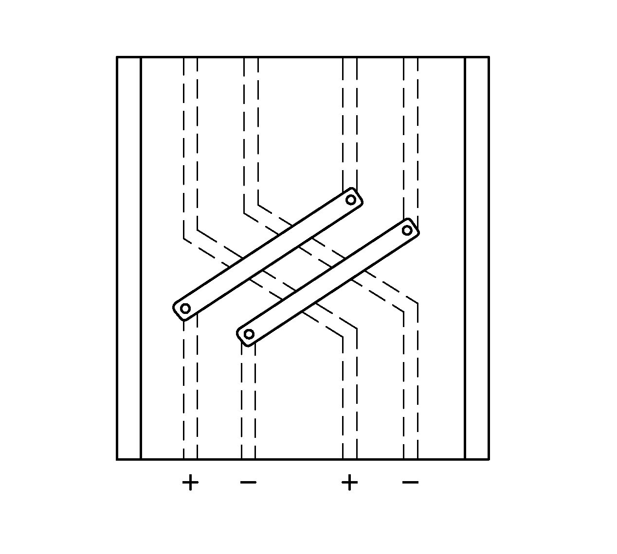
[0137]FIG. 48 is a top plan conceptual view of a reduced impedance suspension circuit having crossing signals according to a reduced impedance, reduced crosstalk suspension circuit. The physical construction of the portion of the circuit shown in FIG. 48 is the same as the physical construction of the portion of the circuit shown in FIG. 46, but the signal polarities are different. More specifically, instead of the signals being arranged in the order of plus, plus, minus, minus as in FIG. 46, the signals are arranged in the order of plus, minus, plus, minus.
[0138]As seen in the figure, all four signal paths extend in parallel; then the plus and minus signal paths for the first differential pair angle away such that they extend in parallel as they cross the plus and minus signal paths for the second differential pair, and the plus and minus signal paths for the second differential pair angle away such that they extend in parallel as they cross the plus and minus signal paths for the ...
third embodiment
[0141]FIG. 49 is a top plan conceptual view of reduced impedance suspension circuit in which each polarity signal is split into multiple paths and the paths are interleaved for reduced impedance. FIG. 50 is a cross sectional view of the suspension circuit of FIG. 49 taken along section line 50-50. In this embodiment the signal path corresponding to conductor 520 carrying the “plus” half of a differential signal pair is split at one end into three different copper conductors: first conductor 521, second conductor 522, and third conductor 523, and recombined at the other end. Those three conductors extend in parallel and carry the first polarity signal of a differential signal pair. Similarly, the signal path corresponding to conductor 530 carrying the “minus” half of the differential signal pair is split at one end into three different copper conductors: fourth conductor 531, fifth conductor 532, and sixth conductor 533, and recombined at the other end. Typically, the places where t...
PUM
 Abstract
Description
Claims
Application Information
 - Generate Ideas
- Intellectual Property
- Life Sciences
- Materials
- Tech Scout
- Unparalleled Data Quality
- Higher Quality Content
- 60% Fewer Hallucinations
Browse by: Latest US Patents, China's latest patents, Technical Efficacy Thesaurus, Application Domain, Technology Topic, Popular Technical Reports.
© 2025 PatSnap. All rights reserved.Legal|Privacy policy|Modern Slavery Act Transparency Statement|Sitemap|About US| Contact US: help@patsnap.com