Forming electrically-conductive patterns using crosslinkable reactive polymers
Active Publication Date: 2016-02-18
EASTMAN KODAK CO
View PDF3 Cites 0 Cited by
Summary
Abstract
Description
Claims
Application Information
AI Technical Summary
This helps you quickly interpret patents by identifying the three key elements:
Problems solved by technology
Method used
Benefits of technology
[0083]The present invention provides fine conductive metal lines without using traditional high-cost semiconductor fabrication methods. It is possible to obtain these advantages because of the use of a unique reactive polymer that can be reacted in the presence of a strong acid to provide a sulfonic acid groups to which metal ions can be complexed, while other moieties in the reactive polymer can provide crosslinking capability.
[0084]The unique reactive polymers provide these advantages and others as they can become water-insoluble in the exposed regions of a polymeric layer, and a water-permeable but water-insoluble pattern can be formed on a suitable substrate. Reactive polymer (and reactive composition) in the non-exposed regions can be readily washed away, if desired, using a suitable solvent. The remaining metal-complexing and crosslinked polymer can then be treated with a catalytic metal ion bath such as silver nitrate where the metal ions will complex with t
Problems solved by technology
As the increase in the use of such devices has exploded in frequency and necessity by displacing older technologies, there has been a concern that electromagnetic radiation emission from such devices may cause harm to the human body or neighboring devices or instruments over time.
However, the use of ITO coatings has a number of disadvantages.
Indium is an expensive rare earth metal and is available in limited supply.
Moreover, ITO is a ceramic material and is not easily bent or flexed and such coatings require expensive vacuum deposition methods and equipment.
In addition, ITO conductivity is relatively low, requiring short line lengths to achieve desired response rates (upon touch).
These smaller segments require additio
Method used
Image
Click on the blue label to locate the original text in one second.
Reading with bidirectional positioning of images and text.
Examples
Example
Invention Example 1
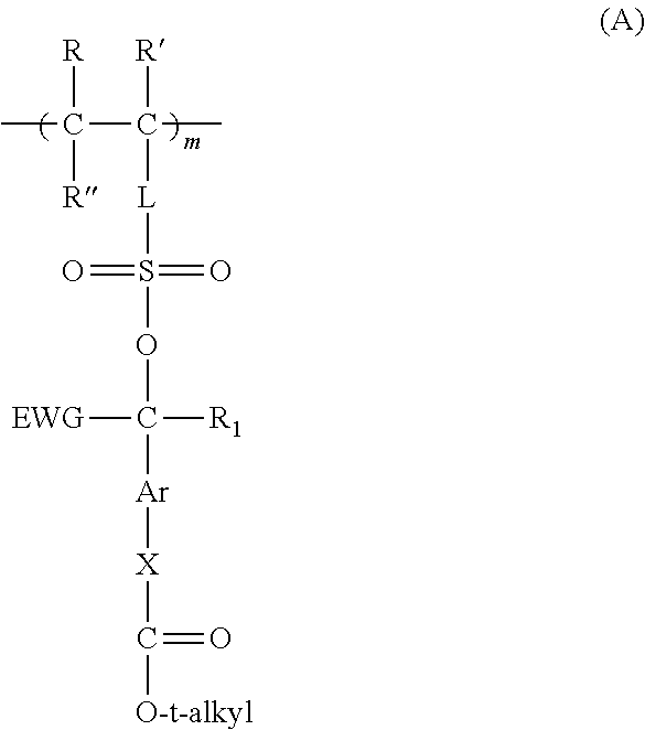
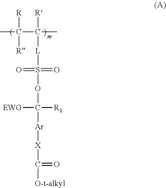
Preparation of a Reactive Polymer A from 3-[(4-t-butoxycarbonyloxy)-α-trifluoromethylbenzylsulfo]propyl methacrylate and glycidyl methacrylate in an 85:15 mol Ratio
[0484]3-[(4-t-Butoxycarbonyloxy)-α-trifluoromethylbenzylsulfo]propyl methacrylate monomer prepared above (2.05 g) and 0.11 g of glycidyl methacrylate were weighed out in a 100 ml single-neck round bottom flask and then dissolved in THF and chloroform to obtain a 20 weight % solids solution. With solution still cloudy, 0.03 g of 2,2′-azodi(2-methylbutyronitrile) (AMBN) initiator was added and the reaction solution was purged with nitrogen for about 30 minutes, capped with a septum, and placed in a preheated oil bath at 65° C. overnight. The reaction solution cleared during heating and was cooled and precipitated into ethanol, filtered, and dried. The resulting white solid was then dissolved in THF, precipitated into ethanol, filtered, and dried in a high vacuum oven at room temperature overnight. The res...
Example
Invention Example 2
Preparation of Reaction Polymer B from 3-[(4-t-butoxycarbonyloxy)-α-trifluoromethylbenzylsulfo]propyl methacrylate, glycidyl methacrylate, and t-butyl methacrylate (64:15:21 mol Ratio)
[0488]3-[(4-t-Butoxycarbonyloxy)-α-trifluoromethylbenzylsulfo]propyl methacrylate monomer prepared above (3.85 g), 0.37 g of t-butyl methacrylate, and 0.27 g of glycidyl methacrylate were weighed out in a 100 ml single-neck round bottom flask and then dissolved in THF to obtain a 25 weight % solids solution. Then, 0.061 g of 2,2′-azodi(2-methylbutyronitrile) (AMBN) initiator was added and the reaction solution was purged with nitrogen for about 30 minutes, capped with a septum, and placed in a preheated oil bath at 65° C. overnight. The reaction solution cleared during heating and was cooled and precipitated into ethanol, filtered, and dried. The resulting white solid was then dissolved in THF, precipitated into ethanol, filtered, and dried in a high vacuum oven at room temperature o...
Example
Invention Examples 3 and 4
Preparation of Reactive Composition Films and Electrically-Conductive Copper Patterns
PUM
Abstract
An electrically-conductive pattern is prepared using a reactive composition having: (1) a reactive polymer; (2) a compound that provides a cleaving acid upon exposure to radiation; and (3) a crosslinking agent that reacts in the presence of the cleaving acid, to provide crosslinking in the reactive polymer. A polymeric layer of the reactive composition is patternwise exposed to provide a polymeric layer comprising non-exposed regions and exposed regions comprising a polymer comprising sulfonic acid or sulfonate groups. The exposed regions are contacted with electroless seed metal ions to form a pattern of electroless seed metal ions, which pattern is reduced to provide a pattern of corresponding electroless seed metal particles. Electrolessly plating is then carried out in the exposed regions. The unique reactive comprises (a) recurring units represented Structure (A) as described in the disclosure, and can also include other recurring units that are crosslinkable or provide other properties.
Description
RELATED APPLICATIONS[0001]Reference is made to the following copending and commonly assigned patent applications, the disclosures of which are incorporated herein by reference:[0002]U.S. Ser. No. 14 / 084,675 that was filed Nov. 20, 2013 by Wexler, Bennett, and Lindner;[0003]U.S. Ser. No. 14 / 084,693 that was filed Nov. 20, 2013 by Irving, Wexler, Bennett, and Lindner;[0004]U.S. Ser. No. 14 / 084,711 that was filed Nov. 20, 2013 by Wexler, Bennett, and Lindner;[0005]U.S. Ser. No. 14 / 071,765 that was filed Nov. 5, 2013 by Brust, Irving, and Falkner;[0006]U.S. Ser. No. 14 / 071,879 that was filed Nov. 5, 2013 by Brust, Irving, Falkner, and Wyand; and[0007]U.S. Ser. No. 14 / ______ filed on even date herewith by Brust, Bennett, and Irving and entitled “Crosslinkable Polymers” (Attorney Docket No. K001845 / JLT).FIELD OF THE INVENTION[0008]This invention relates to a method for forming patterns of a reactive polymer that can be used for forming other material patterns such as electrically-conducti...
Claims
Application Information
Patent Timeline
Application Date:The date an application was filed.
Publication Date:The date a patent or application was officially published.
First Publication Date:The earliest publication date of a patent with the same application number.
Issue Date:Publication date of the patent grant document.
PCT Entry Date:The Entry date of PCT National Phase.
Estimated Expiry Date:The statutory expiry date of a patent right according to the Patent Law, and it is the longest term of protection that the patent right can achieve without the termination of the patent right due to other reasons(Term extension factor has been taken into account ).
Invalid Date:Actual expiry date is based on effective date or publication date of legal transaction data of invalid patent.