Chair

A chair and back frame technology, applied in the field of chairs, can solve problems such as troublesome manual operation, and achieve the effect of easy operation

Active Publication Date: 2013-05-08
KARIMOKU FURNITURE
View PDF7 Cites 9 Cited by
  • Summary
  • Abstract
  • Description
  • Claims
  • Application Information

AI Technical Summary

Problems solved by technology

Therefore, in the process of manually tilting the headrest of the chair relative to the backrest, there is a problem that the manual operation is troublesome.

Method used


Image

  • Chair
  • Chair
  • Chair

Examples


Embodiment 1

[0051] Figure 1 to Figure 11 Example 1 is shown.

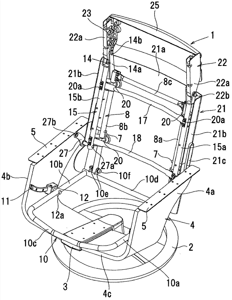
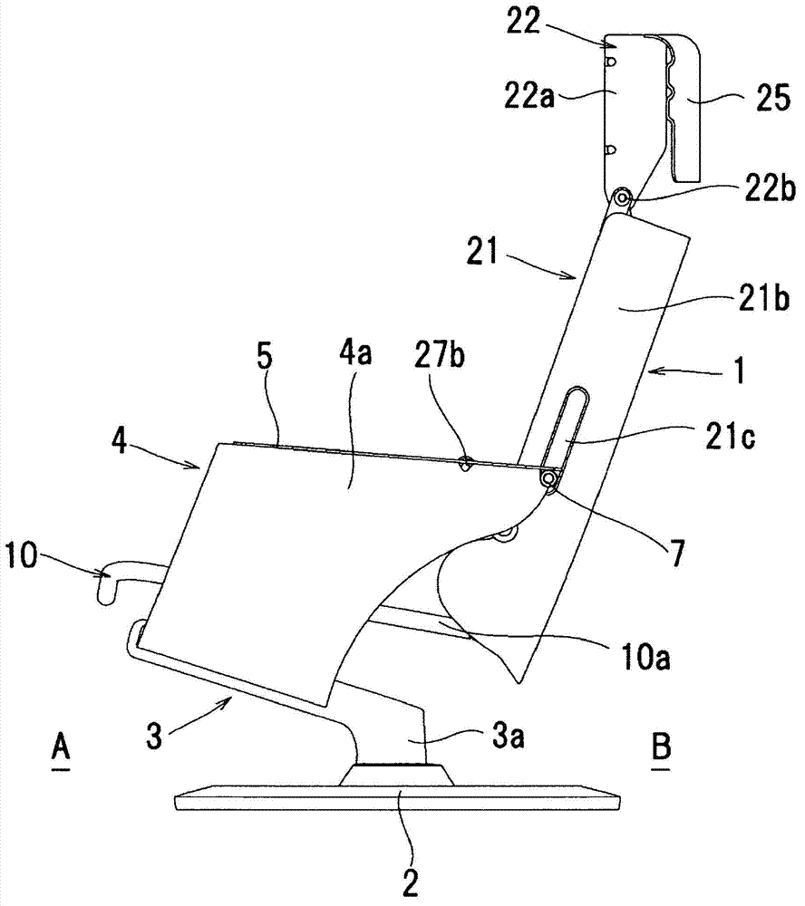
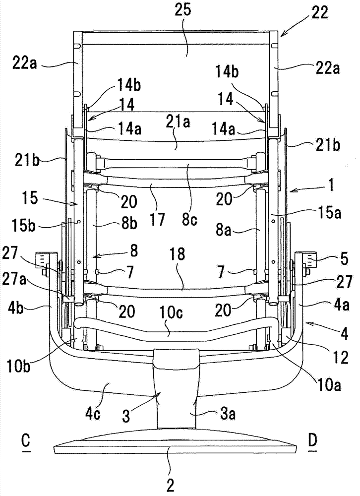
[0052] like Figure 1 ~ Figure 4 As shown, the chair 1 according to the first embodiment of the present invention has a pedestal 2 . The pedestal 2 has a turntable 3 rotatable relative to the pedestal 2 with the vertical direction (vertical direction) as the rotation axis. A chair frame 4 is fixedly arranged on the turntable 3 . Next, connect the seat side of chair 1, that is, with Figure 5 The opposite side of the back frame 8 (backrest 28) is used as the front A, the back frame 8 side is used as the rear B, and the image 3 The left side of is described as left C, and the right side is described as right D.

[0053] like Figure 1 ~ Figure 4 As shown, the chair frame 4 has two side frames 4a, 4b and a lower frame 4c spanned between the lower ends of the two side frames 4a, 4b. The two side frames 4a, 4b and the lower frame 4c are integrally formed. In the center of the lower part of the above-mentioned lower frame 4...

Embodiment 2

[0095] Figure 12 to Figure 14 Example 2 is shown.

[0096] In the second embodiment, as in the first embodiment, the sliding frame 15 is moved along the vertical axis of the back frame 8 (the axis of the side frames 8a and 8b of the back) relative to the horizontal plane at an inclination angle β. In the structure of the axial movement of the side frames 8a, 8b, the angle α of the front surface of the head frame 22 with respect to the axis of the side frames 8a, 8b of the above-mentioned back is changed according to the inclination angle β of the above-mentioned back frame 8. The method is an embodiment different from the above-mentioned embodiment 1.

[0097] In this embodiment 2, if Figure 12 to Figure 14 As shown, the head frame 35 is provided so as to be rotatable in the front and rear directions on the upper end portions of the slide side frames 15 a and 15 b centered on a head shaft 35 c provided horizontally in the left-right (CD) direction. The rear B side of the ...

Embodiment 3

[0111] Figure 15 to Figure 17 Example 3 is shown.

[0112] In the third embodiment, as in the first and second embodiments, the sliding frame 15 is moved in the axial direction of the side frames 8a and 8b on the back according to the inclination angle β of the vertical axis of the back frame 8 relative to the horizontal plane. In this structure, the method of changing the angle α of the front surface of the head frame 45 with respect to the axes of the side frames 8a and 8b of the back is different from the first and second embodiments described above in accordance with the inclination angle β of the back frame 8. the embodiment.

[0113] In Embodiment 3, the fixed head member 42 fixedly arranged on the upper end of the sliding side frame 15a is formed in a plate shape, and a curved guide groove 43 is formed on the fixed head member 42 through the front and back. The curved guide groove 43 can be formed so that at least the outer side of the fixed head member 42 is open, a...


PUM


Abstract

To raise the headrest of a chair in relation to the backrest thereof, and make it possible for the line of sight of a seated person to be oriented forward, in the case of wanting to orient the line of sight forward when slightly reclining the backrest of the chair from an upright position, and to recline the headrest of the chair in relation to the backrest, in the case of wanting to significantly recline the backrest and attain a sleeping posture, a chair is configured in the following manner: the chair has a reclinable / straightenable back frame (8), and a head frame (22) that is reclinable / straightenable in relation to the back frame (8); the head frame (22) rises in relation to the back frame (8) as the back frame (8) reclines from the upright position, but after the angle (a) of the front surface of the head frame in relation to the vertical axis of the back frame reaches a prescribed angle, the head frame (22) reclines in relation to the back frame (8) as the back frame (8) reclines further; in addition, the head frame (22) rises in relation to the back frame (8) as the back frame (8) rises from the reclined position, but after the angle (a) reaches the prescribed angle, the head frame (22) reclines in relation to the back frame (8) as the back frame (8) rises further.

Description

technical field [0001] The present invention relates to chairs. Background technique [0002] Conventionally, there is known a chair including a backrest rotatably provided in the front-rear direction of the chair by a support shaft fixed to the rear of the chair, and a headrest rotatably provided in the front-rear direction on the upper portion of the backrest. , the more the backrest is tilted backward, the more gradually the headrest rises relative to the backrest (see Patent Document 1). [0003] Patent Document 1: Japanese Patent No. 3618443 [0004] With the conventional chair mentioned above, when the occupant comfortably watches TV or the like by tilting the backrest of the chair backward slightly from its upright state, the more the backrest of the chair is tilted, the more gradually the headrest of the chair will move relative to the backrest. Therefore, even in the state where the backrest of the chair is slightly tilted, the occupant can easily visually recogni...

Claims


Application Information

Patent Timeline
Patent Type & Authority Applications(China)
IPC IPC(8): A47C1/036A47C7/38
CPCA47C1/03294A47C1/03205A47C1/036A47C7/38A47C7/46A47C31/126
Inventor 石田大介神谷成昭铃木健太郎长谷田未弦
Owner KARIMOKU FURNITURE
Why Eureka
Try Eureka