Chair
A chair and back frame technology, applied in the field of chairs, can solve problems such as troublesome manual operation, and achieve the effect of easy operation
- Summary
- Abstract
- Description
- Claims
- Application Information
AI Technical Summary
Problems solved by technology
Method used
Image
Examples
Embodiment 1
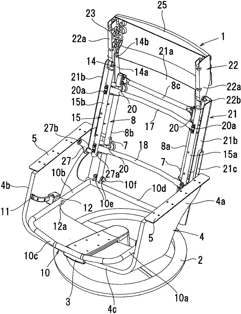
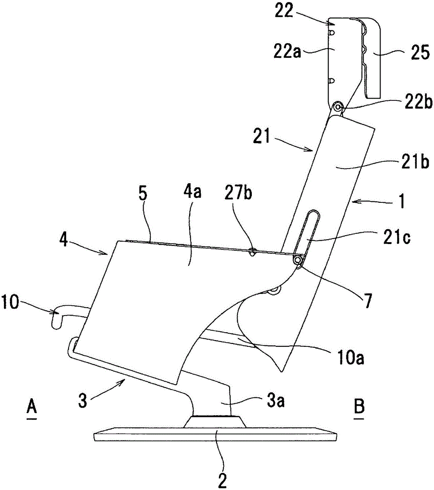
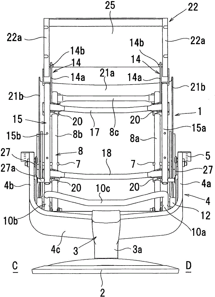
[0051] Figure 1 to Figure 11 Example 1 is shown.
[0052] like Figure 1 to Figure 4 As shown, the chair 1 according to the first embodiment of the present invention has a pedestal 2 . The pedestal 2 has a turntable 3 rotatable relative to the pedestal 2 with the vertical direction (vertical direction) as the rotation axis. A chair frame 4 is fixedly arranged on the turntable 3 . Next, connect the seat side of chair 1, that is, with Figure 5 The opposite side of the back frame 8 (backrest 28) is used as the front A, the back frame 8 side is used as the rear B, and the image 3 The left side of is described as left C, and the right side is described as right D.
[0053] like Figure 1 to Figure 4 As shown, the chair frame 4 has two side frames 4a, 4b and a lower frame 4c spanned between the lower ends of the two side frames 4a, 4b. The two side frames 4a, 4b and the lower frame 4c are integrally formed. In the center of the lower part of the above-mentioned lower frame...
Embodiment 2
[0095] Figure 12 to Figure 14 Example 2 is shown.
[0096] In the second embodiment, as in the first embodiment, the sliding frame 15 is moved along the vertical axis of the back frame 8 (the axis of the side frames 8a and 8b of the back) relative to the horizontal plane at an inclination angle β. In the structure of the axial movement of the side frames 8a, 8b, the angle α of the front surface of the head frame 22 with respect to the axis of the side frames 8a, 8b of the above-mentioned back is changed according to the inclination angle β of the above-mentioned back frame 8. The method is an embodiment different from the above-mentioned embodiment 1.
[0097] In this embodiment 2, if Figure 12 to Figure 14 As shown, the head frame 35 is provided so as to be rotatable in the front and rear directions on the upper end portions of the slide side frames 15 a and 15 b centered on a head shaft 35 c provided horizontally in the left-right (CD) direction. The rear B side of the ...
Embodiment 3
[0111] Figure 15 to Figure 17 Example 3 is shown.
[0112] In the third embodiment, as in the first and second embodiments, the sliding frame 15 is moved in the axial direction of the side frames 8a and 8b on the back according to the inclination angle β of the vertical axis of the back frame 8 relative to the horizontal plane. In this structure, the method of changing the angle α of the front surface of the head frame 45 with respect to the axes of the side frames 8a and 8b of the back is different from the first and second embodiments described above in accordance with the inclination angle β of the back frame 8. the embodiment.
[0113] In Embodiment 3, the fixed head member 42 fixedly arranged on the upper end of the sliding side frame 15a is formed in a plate shape, and a curved guide groove 43 is formed on the fixed head member 42 through the front and back. The curved guide groove 43 can be formed so that at least the outer side of the fixed head member 42 is open, a...
PUM
 Abstract
Description
Claims
Application Information
 - R&D
- Intellectual Property
- Life Sciences
- Materials
- Tech Scout
- Unparalleled Data Quality
- Higher Quality Content
- 60% Fewer Hallucinations
Browse by: Latest US Patents, China's latest patents, Technical Efficacy Thesaurus, Application Domain, Technology Topic, Popular Technical Reports.
© 2025 PatSnap. All rights reserved.Legal|Privacy policy|Modern Slavery Act Transparency Statement|Sitemap|About US| Contact US: help@patsnap.com


