Printing device, printing method and program thereof
A technology of a printing device and a printing head, which is applied in the field of printing technology, can solve problems such as ink drop formation position deviation, and achieve the effect of suppressing brightness changes
- Summary
- Abstract
- Description
- Claims
- Application Information
AI Technical Summary
Problems solved by technology
Method used
Image

Examples
no. 1 Embodiment
[0063] A first embodiment of the present invention will be described.
[0064] A-1. Device composition:
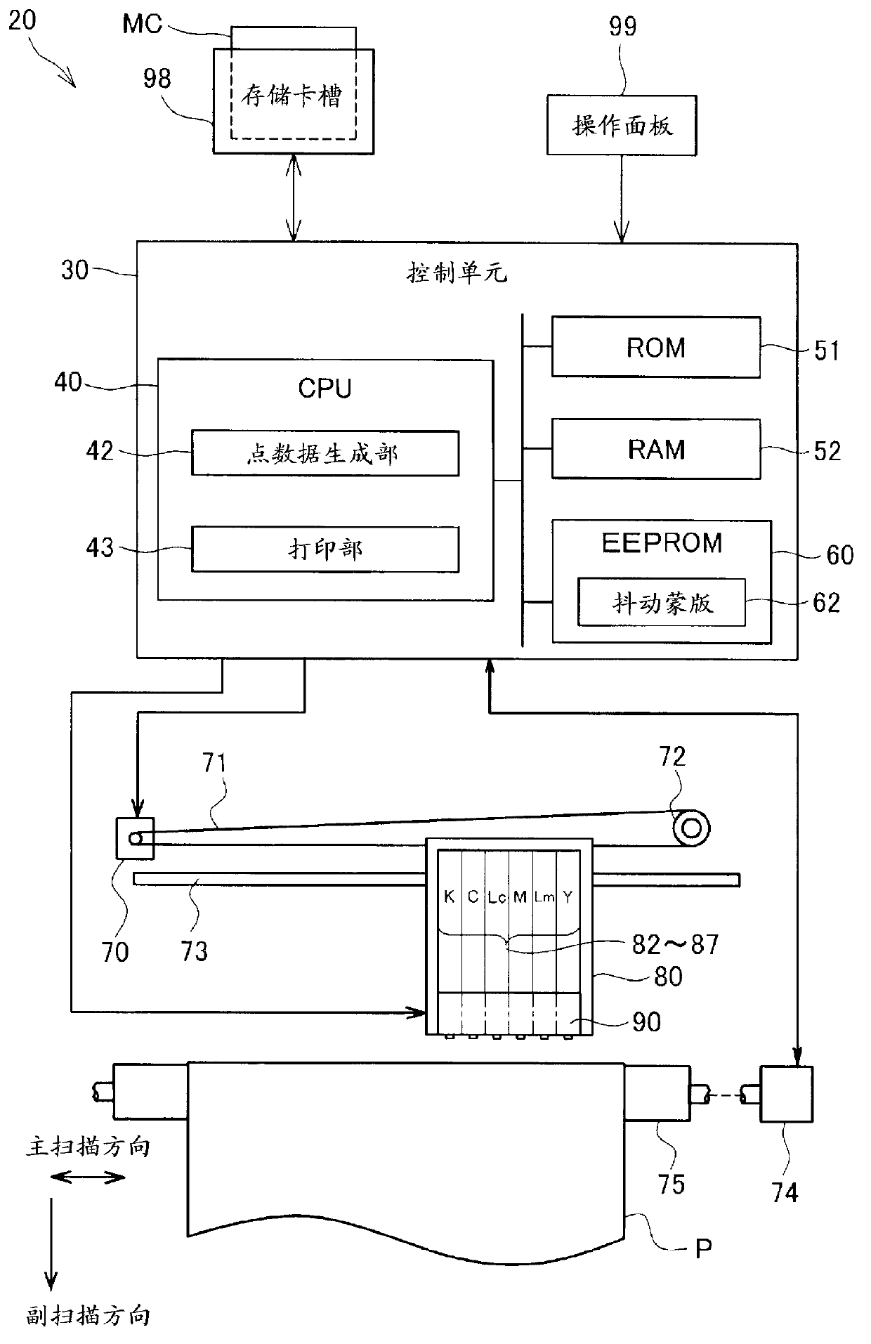
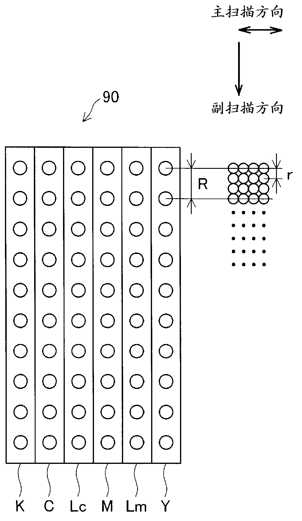
[0065] figure 1 It is a schematic configuration diagram of the printer 20 as the first embodiment of the present invention. The printer 20 is a serial ink-jet printer that performs bidirectional printing. As shown in the figure, the printer 20 has a mechanism for conveying the printing paper P by the paper feed motor 74, and the carriage 80 is moved along the axis of the platen cylinder 75 by the carriage motor 70. A mechanism for reciprocating movement, a mechanism for driving the print head 90 mounted on the carriage 80 to eject ink and dot formation, management and communication between the paper feed motor 74 , the carriage motor 70 , the print head 90 and the operation panel 99 The control unit 30 constitutes the exchange of signals.
[0066] The mechanism for reciprocating the carriage 80 in the axial direction of the platen cylinder 75 consists of a slide shaft ...
no. 2 Embodiment
[0153] D-1. Jitter mask:
[0154] Next, a second embodiment of the present invention will be described. The hardware of the printer 20 as the second embodiment is the same as that of the first embodiment (refer to figure 1 ). Also, the print control processing in the printer 20 ( Figure 4 ) are the same except for the dithering mask used in halftoning. The second embodiment also performs halftone processing by the so-called dithering method.
[0155] The difference between the dither mask used in the second embodiment and the dither mask used in the first embodiment is as follows.
[0156] (1) What both have in common:
[0157] · Dither masks are all 64×64 in size.
[0158] ・Both are dispersion-type dither masks that prioritize dispersion.
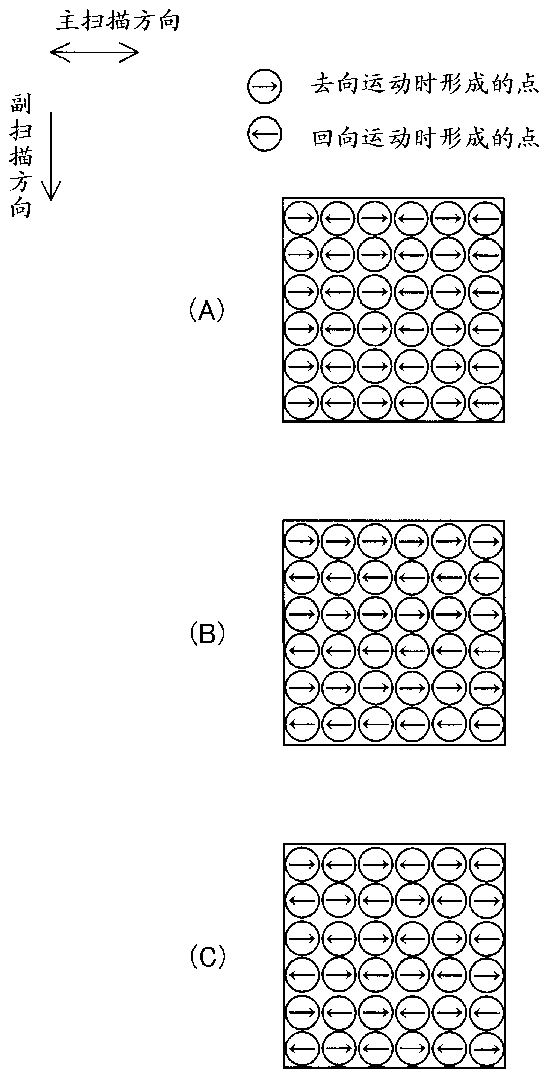
[0159] · When the formation positions of the dots of the forward movement and the backward movement deviate, the changes in the CIEL*a*b* color space all satisfy the following conditions (A) to (C).
[0160] (A) When the printed ...
example 1
[0210] In the second embodiment, it is shown that in the above-mentioned step S331, the pixel group of the printed image is divided into a pixel group composed of forward moving points and a pixel group composed of backward moving points, with respect to the virtual dithering mask The threshold value arrangement of 61 is a configuration in which the threshold value corresponding to any one pixel group is shifted by a predetermined pixel amount in a predetermined direction to generate a dither mask 62 . However, the divided pixel groups are not limited to the above examples, as long as they are pixel groups with different printing conditions.
[0211] For example, when the print head 90 prints an image in a predetermined area through a plurality of main scans, the pixel group of the printed image may be divided into pixels that form dots in different main scans among the plurality of main scans. Group. For example, through paths 1 to 4, the region composition of the image is c...
PUM
 Abstract
Description
Claims
Application Information
 - R&D Engineer
- R&D Manager
- IP Professional
- Industry Leading Data Capabilities
- Powerful AI technology
- Patent DNA Extraction
Browse by: Latest US Patents, China's latest patents, Technical Efficacy Thesaurus, Application Domain, Technology Topic.
© 2024 PatSnap. All rights reserved.Legal|Privacy policy|Modern Slavery Act Transparency Statement|Sitemap