
Window hinge joint method for erection of suspension bridge steel truss stiffening girder

A technology of stiffened beams and steel trusses, which is applied in bridge construction, bridge erection/assembly bridges, etc., and can solve the problems of long construction period, unfavorable stress on the stiffened beam structure, and the inability to ensure stress-free installation at the temporary joint of the stiffened beam section, etc. problem, to achieve the effect of process improvement

Inactive Publication Date: 2013-05-15
SOUTHWEST JIAOTONG UNIV
View PDF5 Cites 3 Cited by
  • Summary
  • Abstract
  • Description
  • Claims
  • Application Information

AI Technical Summary

Problems solved by technology

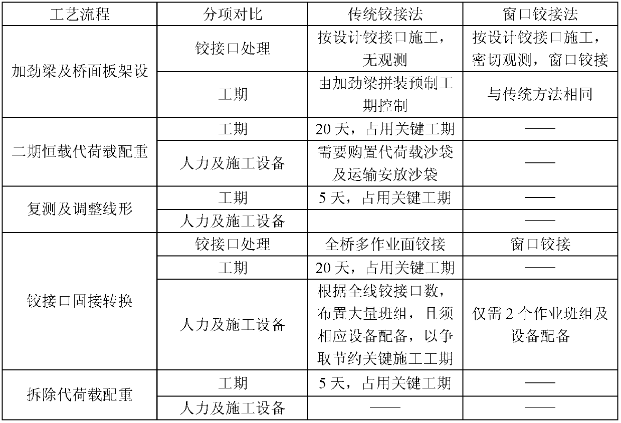
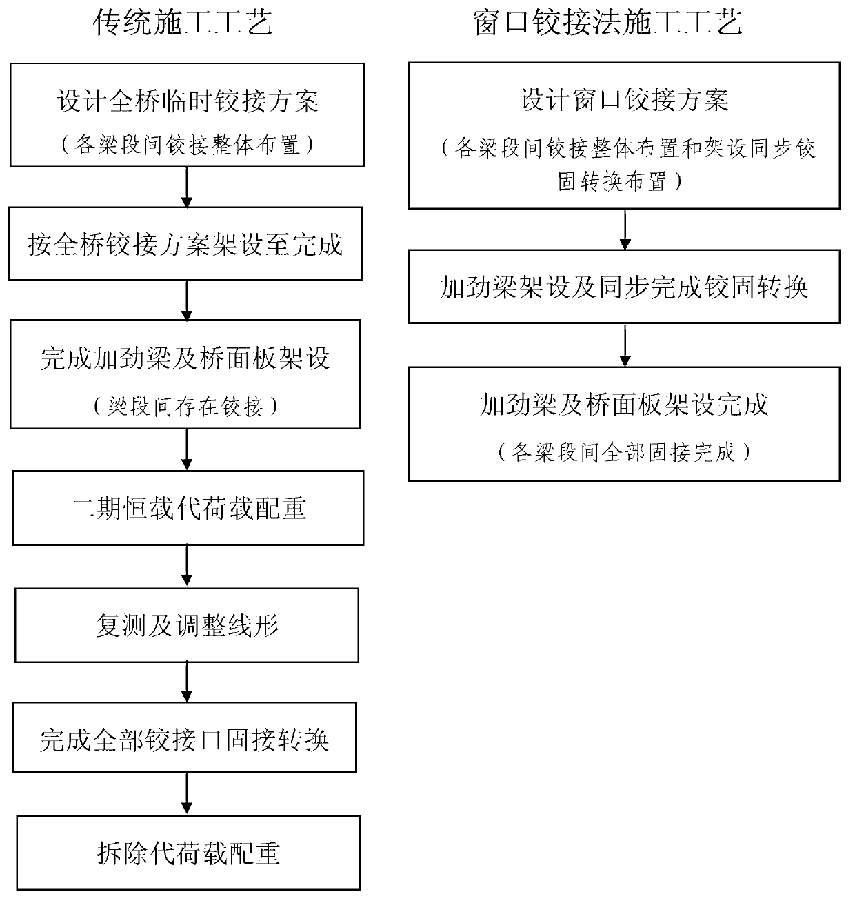
[0002] At present, the commonly used construction method for steel truss stiffened girder erection of suspension bridges is to adopt single-segment temporary hinged or segmented temporary hinged. The alignment of the completed bridge is in an upward arching state, and the distance between the temporary hinge joints cannot meet the requirements for hinge-to-solid conversion. It is necessary to carry out counterweighting with the second-phase dead load and other loads (sandbags, gravel, etc.), and carry out all temporary joints after passing the alignment test. Hinge-fixed conversion construction of the hinged section, after the hinged-fixed conversion is completed, the subsequent bridge deck system construction will be carried out
Among them, the substitute weight counterweight and hinge-fix conversion both occupy the key construction period, the construction period is relatively long, the efficiency of simultaneous construction is low, and a large amount of manpower, counterweight materials and mechanical equipment are required; and the temporary hinge joint of the stiffened beam section cannot be guaranteed. To achieve stress-free installation, usually due to errors such as weighing and measurement, it is necessary to force the installation of the hinge joint when the hinge is converted, resulting in a large installation stress, which is unfavorable to the stress of the stiffened beam structure

Method used


Image

  • Window hinge joint method for erection of suspension bridge steel truss stiffening girder
  • Window hinge joint method for erection of suspension bridge steel truss stiffening girder

Examples


Embodiment Construction

[0012] specific implementation plan

[0013] Compared figure 1 It can be seen that in the erection stage of the stiffened beam, the overall scheme of the temporary hinge of the whole bridge of the stiffened beam is reasonably set according to the lifting capacity of the construction equipment and the force requirements of the stiffened beam structure. During the construction process or during the installation of the bridge deck, using the linear changes of the installed stiffening beams during the construction process, when the distance between the temporary hinge joints meets the requirements, and the internal force of the subsequent construction process after consolidation will not exceed the force limit of the component, the hinge will be carried out immediately. Then, the temporary joints are fixed step by step; before all the stiffening girders are erected or the bridge deck is installed, all the temporary joints are completed. Therefore, in the traditional construction ...


PUM


Abstract

The invention discloses a window hinge joint method for erection of a suspension bridge steel truss stiffening girder. At the erection stage of the steel truss stiffening girder, according to construction conditions and the stress requirement of the stiffening girder, temporary hinge joint is adopted between some stiffening girder sections. Linear changes of the stiffening girder at the erection stage of the stiffening girder or at the installation stage of a bridge deck slab are utilized to achieve gradual unstressed solid joint transformed from temporary hinge joint, and transformation from all temporary hinge joint to solid joint at the erection stage of the stiffening girder or at the installation stage of the bridge deck slab is realized.

Description

technical field [0001] The invention relates to a bridge construction method, in particular to the technical field of a connection method between beam sections erected by a steel truss stiffened beam of a suspension bridge. Background technique [0002] At present, the commonly used construction method for steel truss stiffened girder erection of suspension bridges is to adopt single-segment temporary hinged or segmented temporary hinged. The alignment of the completed bridge is in an upward arching state, and the distance between the temporary joints cannot meet the requirements for hinge-to-solid conversion. It is necessary to carry out counterweighting with the second-phase dead load and other loads (sandbags, gravel, etc.), and carry out all temporary joints after passing the alignment test. The hinge-to-fix conversion construction of the hinged segment, after the hinge-to-fix conversion is completed, the subsequent bridge deck system construction will be carried out. A...

Claims


Application Information

Patent Timeline
IPC IPC(8): E01D21/00
Inventor 闫勇沈锐利张念来唐茂林
Owner SOUTHWEST JIAOTONG UNIV
Learn More