Method for testing deflection/longitudinal displacement change of bridge based on four-quadrant position detector

A four-quadrant detector and bridge deflection technology, which is applied in the direction of instruments, measuring devices, and optical devices, can solve the problems of inability to meet the requirements of bridge deflection measurement and low measurement accuracy, so as to make up for the decrease in measurement accuracy and ensure accuracy , low cost effect

Inactive Publication Date: 2012-07-11
DALIAN MARITIME UNIVERSITY
View PDF2 Cites 32 Cited by
  • Summary
  • Abstract
  • Description
  • Claims
  • Application Information

AI Technical Summary

Problems solved by technology

However, at present, ultrasonic liquid level detectors are generally used for liquid level detection to complete deflection measurement, and the measurement accuracy is relatively low, only at the centimeter level
By comparing the above several bridge deflection measurement methods, we can know that none of the existing deflection measurement methods can meet the requirements of bridge deflection measurement

Method used


Image

  • Method for testing deflection/longitudinal displacement change of bridge based on four-quadrant position detector
  • Method for testing deflection/longitudinal displacement change of bridge based on four-quadrant position detector
  • Method for testing deflection/longitudinal displacement change of bridge based on four-quadrant position detector

Examples


Embodiment 1

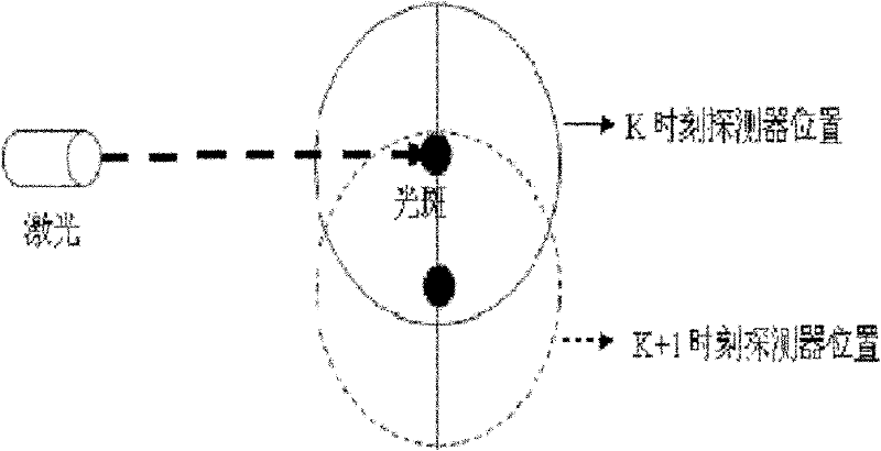
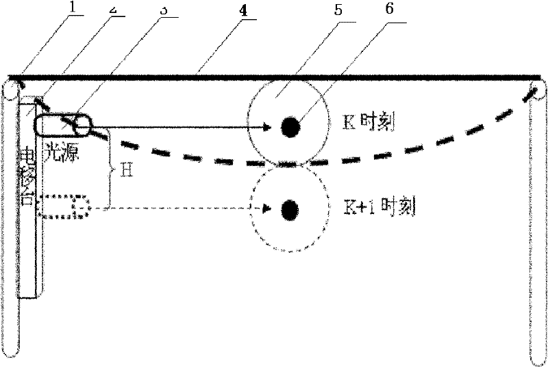
[0039] like figure 2 shown. The span aperture of the bridge 4 is within 300m, the detector 5 is fixed in the middle of the bridge 4, the laser light source 3 is installed on the bridge pier 1 through the electric shift table 2, and the deflection value is measured. It is ensured that the light spot 6 of the laser hits the photosensitive surface of the detector 5 vertically. At time K (before the deflection of the bridge changes), the light spot 6 hits the center of the detector 5, and at time K+1 (after the deflection of the bridge changes), the light spot 6 cannot hit the detector due to the large deflection change of the bridge 4 5 on the photosensitive surface, at this time, the position of the light source 3 is adjusted by controlling the electric shift stage 2, so that the light spot 6 hits the center of the photosensitive surface of the detector 5 again. The distance H moved by the electric moving stage 2 is obtained by measurement. This H value is the deflection cha...

Embodiment 2

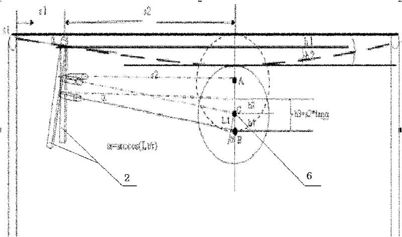
[0041] like image 3 shown. The detector 5 is fixed at the middle position of the bridge 4, and the light source 3 is fixed at an appropriate distance from the detector 5 to ensure measurement accuracy. When the deflection of the bridge 4 changes, the deflection value of the point to be measured is H=h1+h2, wherein h1 is the deflection change value of the electric moving station 2 when the deflection of the bridge 4 changes, and h2 is the position of the detector 5 when the deflection of the bridge 4 changes The change value of the deflection at the position relative to the electric shift stage 2. Since there is a certain distance between the electric moving platform 2 and the bridge pier 1, an angle α will be formed between the end point of the bridge 4 and the bridge deck after the deflection of the bridge 4 changes, and an angle α will be formed between the electric moving platform 2 and the original vertical direction; similarly, There is also an angle α between the ligh...


PUM


Abstract

The invention discloses a method for testing a deflection/longitudinal displacement change of a bridge based on a four-quadrant position detector. The method is characterized by comprising the following steps: firstly, the four-quadrant position detector is installed in the centre of the bridge or other points to be tested at the bottom of a bridge deck; a laser source is installed on a pier and/or a certain point below the bridge deck through an electric displacement table; then, testing is carried out by matching the four-quadrant detector with the laser source, so that the light spot of laser is over against the centre of the detector; when the deflection of the bridge deck changes, the four-quadrant detector longitudinally moves together with the point to be tested; the light spot position, formed on the four-quadrant detector, of the laser moves oppositely relative to the detector; and different position coordinates of the light spot on the detector before and after the deflection of the bridge changes and light spot position variable quantity on the four-quadrant detector, namely deflection position variable quantity of the point to be tested on the bridge deck can be calculated. The method disclosed by the invention has the advantages of simple structure, good controllability and high precision and is capable of realizing real-time online test of the deflection/longitudinal displacement of the bridge.

Description

technical field [0001] The invention relates to exploration or detection with an optical device, in particular to a method for testing bridge deflection changes with a four-quadrant position detector. Background technique [0002] As an important connection facility of the transportation network, the bridge has an extremely important position in the transportation and economic development of our country. In the process of bridge construction, due to unreasonable bridge structure design, construction and management and lax management; The influence of factors and the load of the bridge itself and the dynamic load generated under the full-load operating condition of the bridge make it inevitable that various deformations and damages will occur on the bridge, and even bridge collapse and fracture will occur. Due to the existence of these many unfavorable factors, there are great potential safety hazards in the construction and maintenance of bridges, so that bridge collapse ac...

Claims


Application Information

Patent Timeline
Patent Type & Authority Applications(China)
IPC IPC(8): G01B11/03G01B11/16
Inventor 董丽丽许文海李瑛
Owner DALIAN MARITIME UNIVERSITY
Why Eureka
Try Eureka