Composite bridge superstructure with precast deck elements

a composite bridge and superstructure technology, applied in bridge construction, bridge materials, construction, etc., can solve the problems of needing to prestress the entire cross section, excessive use of prestressing steel, so as to save maintenance costs, save prestressing steel, and improve the riding quality of the deck

Inactive Publication Date: 2002-10-29
MAIRANTZ BENJAMIN
View PDF27 Cites 33 Cited by
  • Summary
  • Abstract
  • Description
  • Claims
  • Application Information

AI Technical Summary

Benefits of technology

It is an additional advantage of the invention that since the substantially separate longitudinal prestressing of the deck structure and the beams is highly effective, considerable saving of prestressing steel is achieved.
In accordance with a further advantage of the invention, the natural compressing of the deck structure and the cast-in-place concrete layer result in crack-free condition and better riding quality of the deck, thereby eliminating the well known drawbacks of additional post-tensioning required to maintain compression over the joints, and saving maintenance costs.
In accordance with yet another advantage of the inventive method, the proposed separation between deck structure and beam construction enables simplification of the formworks which in turn results in substantial saving of costs. It is an additional advantage that the bridge deck structure is substantially comprised of simple precast elements whereby pouring of the deck as a whole or in parts in situ is avoided.
Additional features and advantages of the invention will become apparent from the following drawings and description.

Problems solved by technology

The main drawback of all the above described methods is the excessive need for post-tensioning which is repeated at several stages to accomodate temporary conditions during construction.
Another drawback of the existing methods is the excessive use of prestressing steel resulting from the need to prestress the entire cross section including parts under permanent compression.
Once again in this method the main drawback is the considerable prestressing loss due to shrinkage and creep that severely reduce the effectiveness of the longitudinal prestressing of the deck.
Another drawback of this method is the need to delay the establishment of composite action in order to allow for a certain amount of free creep and shrinkage deformation of the slabs, resulting in a substantial delay of construction.

Method used


Image

  • Composite bridge superstructure with precast deck elements
  • Composite bridge superstructure with precast deck elements
  • Composite bridge superstructure with precast deck elements

Examples


Embodiment Construction

Details of the invention shall now be described in accordance with a preferred embodiment and with reference to the drawings. In the preferred embodiment the bridge superstructure consists of a single composite member with a pair of prestressed beams.

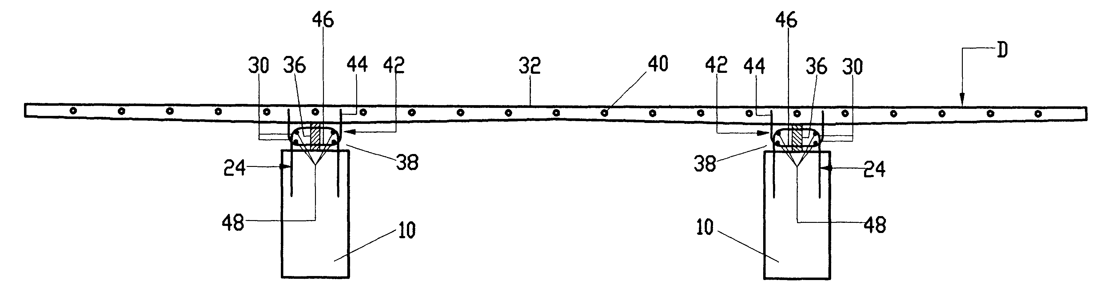
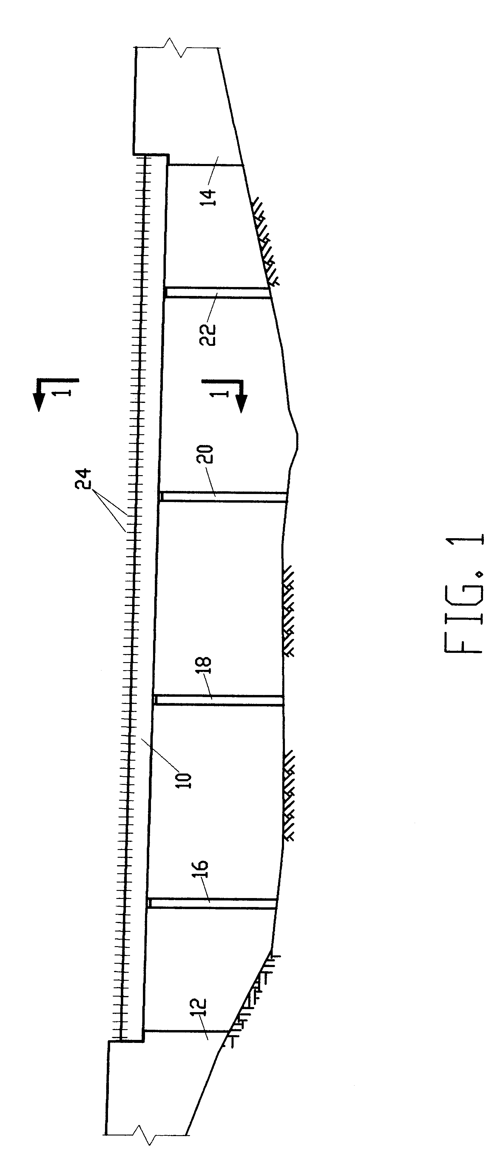
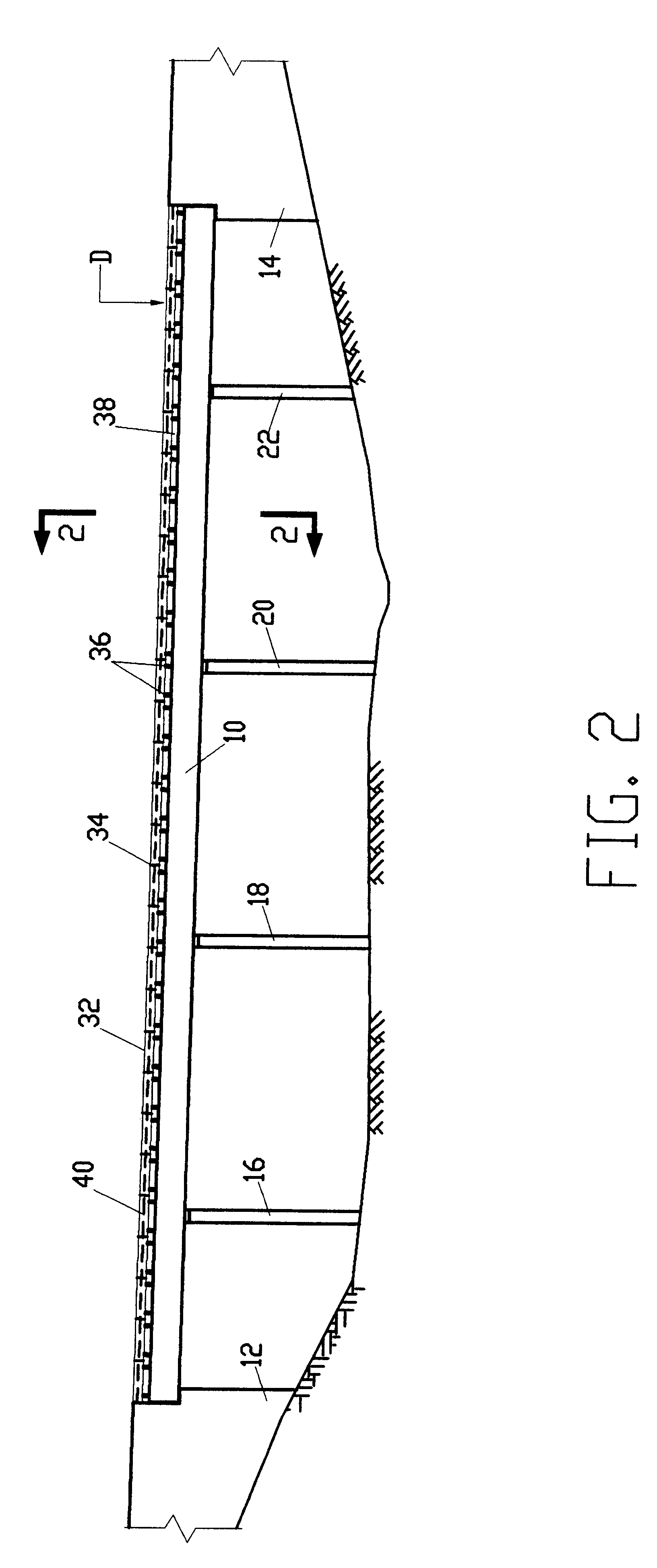
As shown in FIG. 1, construction of the composite member begins by erecting a pair of prestressed beams 10 (of which only the proximally disposed beam is shown) spanning the gap between abutments 12 and 14. A plurality of pre-erected piers 16, 18, 20 and 22 are used to support the prestressed beams 10 as known in the art. A plurality of shear stirrup means 24 are disposed along each of the prestressed beams 10 respectively.

As seen best in the cross-sectional view of FIG. 4 taken along section lines 1--1 of FIG. 1, each of the shear stirrup means 24 is substantially U-shaped, with a pair of legs 26 embedded in one of the prestressed beams 10 and a loop 28 having paired bends 30 horizontally spaced from each other, projecting above the pr...


PUM


Abstract

A method for constructing a composite bridge superstructure of simple precast elements. According to the method, the bridge superstucture is comprised of one or more prestressed beams aligned substantially parallel to the bridge longitudinal axis. On top of the prestressed beams, there is placed a plurality of full width, precast deck slabs forming the bridge deck, with the precast deck slabs being transversely disposed side by side, with adjacent slabs attached by joints to complete the bridge deck structure. The deck slabs are spaced from the beams by spacing devices, such that a gap is left between the beams and the deck slabs and the bridge deck structure is prestressed separately from the beams. Subsequent to the prestressing of the deck structure and the beams, the bridge deck structure is connected to the beams by a concrete layer cast in situ in the gap between the bottom face of the precast deck slabs and the top face of the prestressed beams. The concrete is preferably of the low shrinkage type but normal shrinkage concrete may also be employed. The connection is further reinforced by a plurality of shear stirrups. The method is characterized by separate prestressing of the deck structure and the beams and by natural compression of the connecting concrete layer resulting in significant savings of construction time and costs. The construction sequence according to the method enables the deck structure as well as the cast in place concrete layer connecting the deck structure to the beams to undergo a natural compressing process due to time dependent creep and shrinkage contraction of the beams relative to the connecting layer and the deck structure, thereby eliminating the need to apply additional prestressing. In addition, the substantially separate longitudinal prestressing of the deck structure and the beams is highly effective, achieving considerable saving of prestressing steel. The natural compressing of the deck structure and the cast-in-place concrete layer result in crack-free condition and better riding quality of the deck, thereby eliminating the well known drawbacks of additional prestressing, and saving maintenance costs.

Description

FIELD OF THE INVENTIONThe present invention relates to a method for erection of an elevated prestressed composite bridge superstructure with precast concrete deck elements.BACKGROUND OF THE INVENTIONOne method presently used for the construction of elevated long span concrete bridges involves the use of cast-in-place cantilever segmental construction, wherein the spans are cast segmentally using forms supported by the partly completed construction. According to this method, construction proceeds in opposite directions on each side of an intermediate pier by the balanced cantilever method wherein new segments are post tensioned to the previously completed structure, a closing joint is created and finally the joint structure is further post tensioned to achieve fill continuity.The above method has also been adapted to the use of precast segments instead of cast-in-place segments, wherein individual segments are lifted into position and connected to the already completed work by post-t...

Claims


Application Information

Patent Timeline
Patent Type & Authority Patents(United States)
IPC IPC(8): E01D19/12
CPCE01D19/125E01D2101/28
Inventor MAIRANTZ, BENJAMIN
Owner MAIRANTZ BENJAMIN
Why Eureka
Try Eureka