
Vehicle

Active Publication Date: 2014-12-04
TOYOTA JIDOSHA KK
View PDF17 Cites 9 Cited by
  • Summary
  • Abstract
  • Description
  • Claims
  • Application Information

AI Technical Summary

Benefits of technology

The patent text describes a suspension system for vehicles that improves both steering stability and ride quality without being too expensive. The system uses hydraulic-type shock absorbers with a damping coefficient modification mechanism for the two wheels with the highest movement. By controlling the damping force exerted on this movement, the behavior of the vehicle body can be effectively curbed. The system is easy to configure and uses a control scheme that can be adapted to different vehicles. The system also allows for continuous control of the target damping force and provides superior damping performance even with hydraulic-type shock absorbers.

Problems solved by technology

However, the suspension system disclosed in Patent Document 1, i.e. a suspension system wherein hydraulic-type shock absorbers having a damping coefficient modification mechanism are provided corresponding to all four wheels, is comparatively expensive, and it is thus difficult to equip all vehicles with such a system.

Method used


Image

  • Vehicle
  • Vehicle
  • Vehicle

Examples


embodiment 1

Configuration of the Vehicle

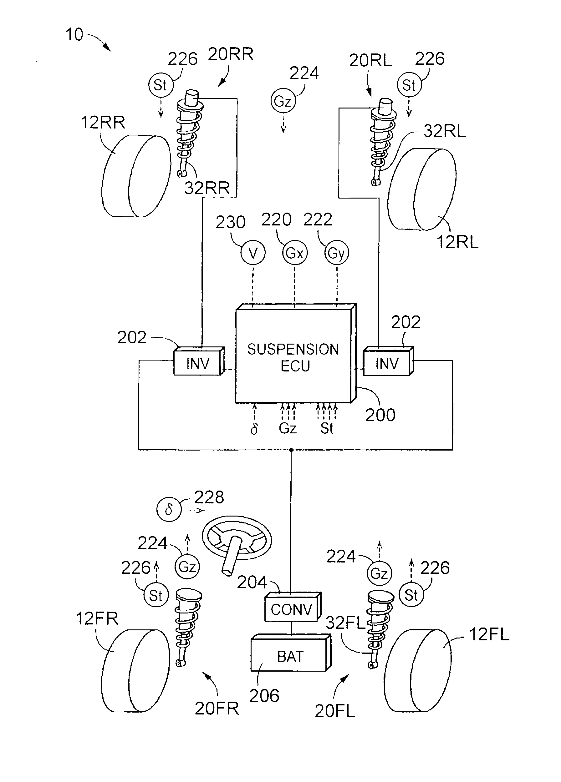
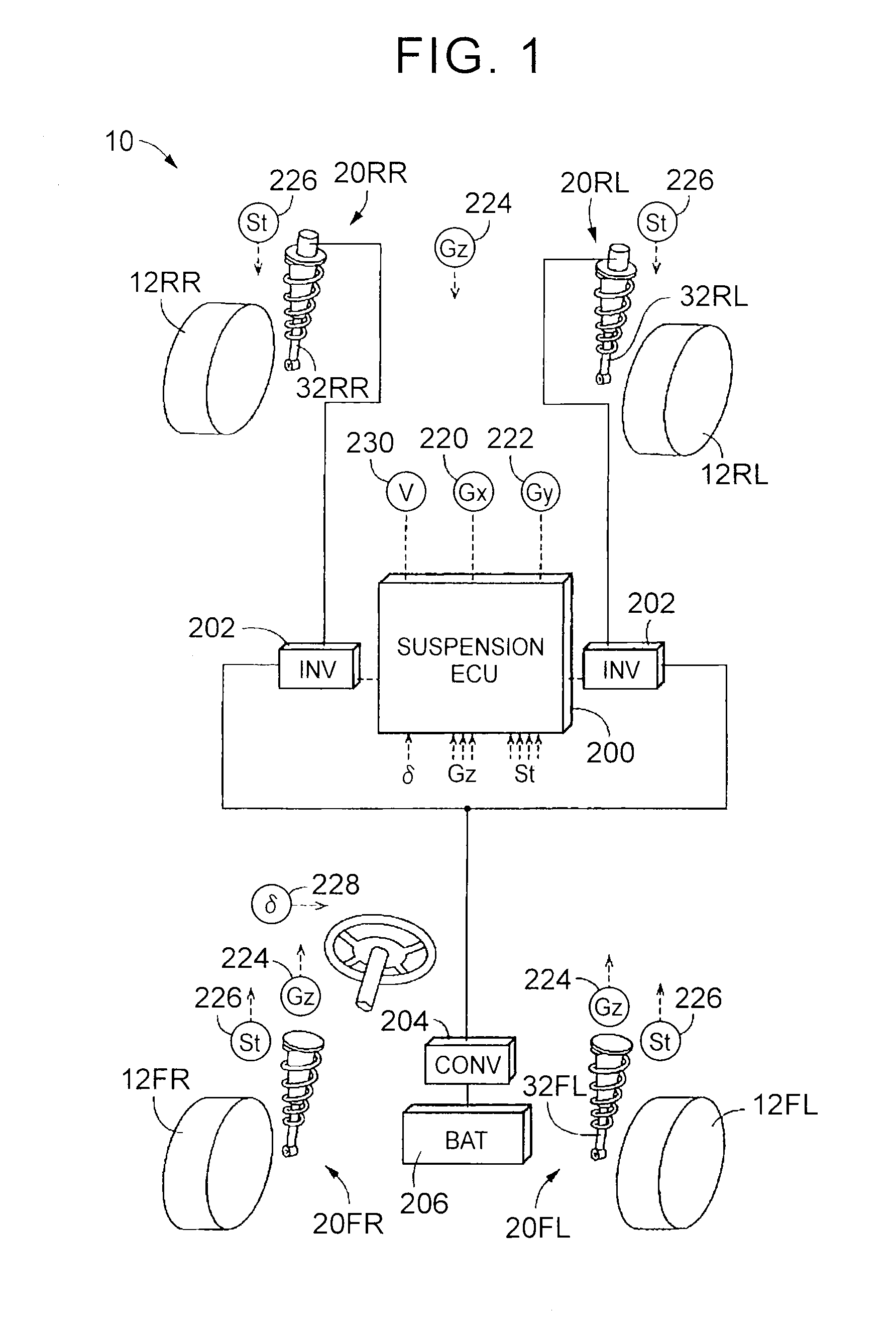
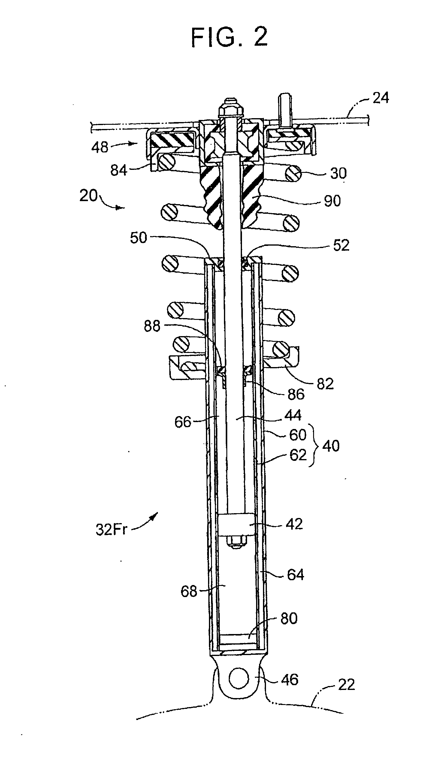
[0060]FIG. 1 illustrates schematically a vehicle 10 being an embodiment of the claimable invention. A suspension system is installed in the vehicle 10. The suspension system is made up of four suspension devices 20, of independent suspension type, corresponding respectively to four wheels 12 that are disposed at four corners of the vehicle 10. Each suspension device 20 is provided between a suspension lower arm 22 that holds a wheel 12 and that makes up part of an unsprung section, and a mount section 24 that is provided in a vehicle body and that makes up part of a sprung section, such that the suspension lower arm 22 and the mount section 24 are connected by the suspension device 20. Herein, the wheels 12 and the suspension devices 20 are generic terms. In those instances where it is necessary to clarify which one from among the four wheels a given wheel 12 or a given suspension device 20 corresponds to, a suffix FL, FR, RL or RR corresponding respectiv...

embodiment 2

[0084]In the vehicle of the second embodiment, as in the case of the vehicle 10 of the first embodiment, the rear wheel-side sprung resonance frequency ωRr is set lower than the front wheel-side resonance frequency ωFr and only shock absorbers corresponding to the rear wheels 12Rr are set to have a modifiable damping coefficient. In the vehicle of the second embodiment, however, shock absorbers 250 that are provided corresponding to the rear wheels 12Rr are not of hydraulic-type, but are electromagnetic-type shock absorbers, having each an electromagnetic motor 252, that generate approach and separation forces, being forces that rely on forces generated by the electromagnetic motor 252 and that are exerted on the sprung section and the unsprung section corresponding to the shock absorbers 250, for drawing the sprung section and the unsprung section closer to or apart from each other. Except for the structure of the rear wheel-side shock absorbers and the control scheme thereof, the ...


PUM


Abstract

A spring constant of each of four suspension springs and a shared load on each of four wheels are adjusted so that a sprung resonance frequency corresponding to two front wheels and a sprung resonance frequency corresponding to two rear wheels are mutually different. From among the four shock absorbers, only two shock absorbers provided corresponding to two wheels of lowered sprung resonance frequency, from among the two front wheels and the two rear wheels have respectively damping coefficient modification mechanisms that modify a damping coefficient serving as a reference of the magnitude of the damping force generated by the two shock absorbers. The behavior of the entire vehicle body can be effectively curbed by controlling the damping force exerted on the comparatively large movement of sprung sections corresponding to the two wheels. Thus a vehicle having both enhanced steering stability and enhanced ride quality can be configured comparatively inexpensively.

Description

TECHNICAL FIELD[0001]The invention relates to a vehicle in which only two wheels on one side, from among two wheels on a front side and two wheels on a rear side, are each provided with a shock absorber having a mechanism that modifies a damping coefficient that serves as a reference of a damping force exerted on an approach and separation movement of a sprung section and an unsprung section.BACKGROUND ART[0002]Suspension systems for vehicles include suspension systems that are provided with shock absorbers, corresponding to respective wheels, each shock absorber having a damping coefficient modification mechanism that modifies a damping coefficient that serves as a reference of a damping force exerted on an approach and separation movement of a sprung section and an unsprung section. For instance, the system disclosed in Patent Document 1 is a suspension system wherein respective hydraulic-type shock absorbers, the damping coefficient of which can be modified by exerting resistance...

Claims


Application Information

Patent Timeline
IPC IPC(8): B60G17/0165B60G17/018
CPCB60G17/018B60G17/0165B60G17/06B60G2400/0531B60G2400/0532B60G2400/0533B60G2400/102B60G2400/252B60G2500/10B60G2400/206B60G2400/821B60G2400/91B60G2800/162B60G2800/916B60G17/00B60G17/015
Inventor YABUMOTO, HIROKAZU
Owner TOYOTA JIDOSHA KK
Learn More