Electrically powered suspension system

Pending Publication Date: 2022-09-22
HONDA MOTOR CO LTD
View PDF0 Cites 0 Cited by
  • Summary
  • Abstract
  • Description
  • Claims
  • Application Information

AI Technical Summary

Benefits of technology

The invention is an electric suspension system for cars that creates a smoother and more exciting ride during sporty driving. It helps to make the car feel like it's part of the driver's body, making turns more confidently.

Problems solved by technology

However, the electrically powered suspension system described in Patent Literature 1 operates such that the control device restrains, regardless of whether sporty driving is being performed, the roll behavior normally that occurs when the vehicle is turning.
Then, in sporty driving, it is not possible for the driver to, on the basis of the roll behavior, feel the timing of the tires to start slipping while performing a turn.
As a result, there is a risk that the driver may feel uncomfortable.

Method used


Image

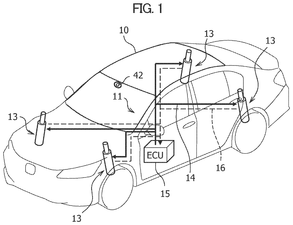
  • Electrically powered suspension system
  • Electrically powered suspension system
  • Electrically powered suspension system

Examples


Embodiment Construction

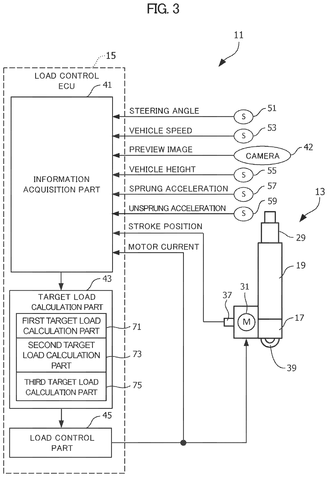
[0017]An electrically powered suspension system 11 according to an embodiment of the present invention will be described in detail below with reference to the drawings as appropriate.

[0018]Note that, in the drawings referenced hereinafter, basically, members having the same function are denoted by the same reference sign. In this case, as a general rule, a redundant description will be omitted. For convenience of explanation, sizes and shapes of components may be schematically illustrated with deformation or in an exaggerated manner.

[0019][Basic Configuration Common to Electrically Powered Suspension Systems 11 According to Embodiments of the Present Invention]

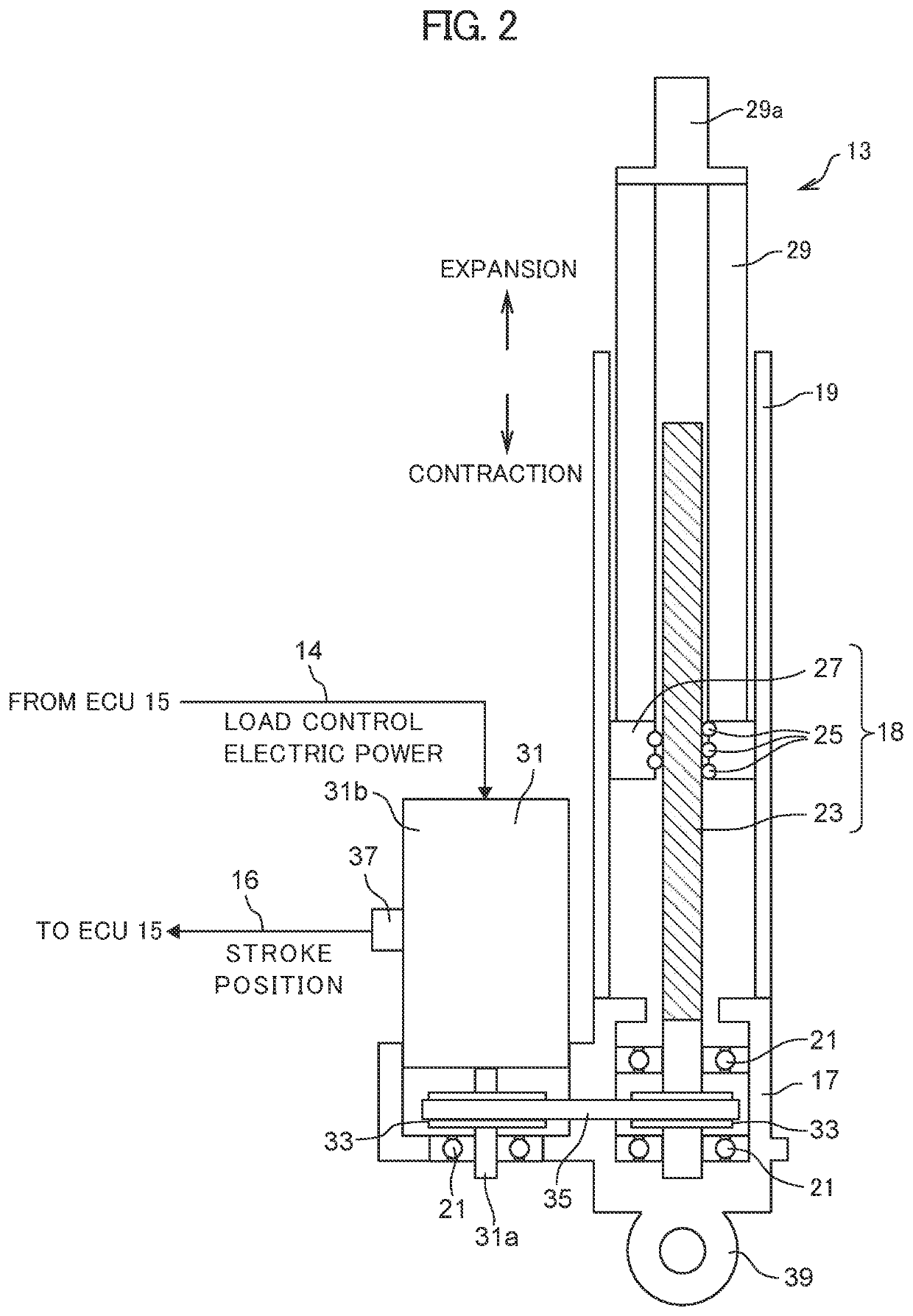
[0020]Firstly, a description will be given of a basic configuration common to the electrically powered suspension systems 11 according to the embodiments of the present invention with reference to FIGS. 1 and 2.

[0021]FIG. 1 is a view illustrating an entire configuration common to the electrically powered suspension systems 11 ...


PUM


Abstract

An electrically powered suspension system includes: an actuator that is provided between a vehicle body and a wheel of a vehicle and generates a load for damping vibration of the vehicle body; an information acquisition part that acquires information on a sprung state amount and a road surface state; a target load calculation part that calculates a first target load related to skyhook control based on the sprung state amount and calculates a second target load related to preview control based on the road surface state; and a load control part. The target load calculation part calculates a third target load related to roll generation control based on a target roll angle and calculates a combined target load into which the first target load, second target load, and third target load have been combined. The load control part performs load control of the actuator using the combined target load.

Description

CROSS-REFERENCE TO RELATED APPLICATIONS[0001]The present application claims the foreign priority benefit under Title 35 U.S.C. § 119 of Japanese Patent Application No. 2021-047965, filed on Mar. 22, 2021, in the Japan Patent Office, the disclosure of which is herein incorporated by reference in its entirety.BACKGROUND OF THE INVENTION1. Field of the Invention[0002]The present invention relates to an electrically powered suspension system including an actuator that is provided between a vehicle body and a wheel of a vehicle and configured to generate a load for damping vibration of the vehicle body.2. Description of Related Art[0003]An electrically powered suspension system including an actuator provided between a vehicle body and a wheel of a vehicle and configured to generate a load for damping vibration of the vehicle body is conventionally known. For example, see Japanese Patent Publication No. 2018-134899 (hereinafter referred to as Patent Literature 1).[0004]The electrically po...

Claims


Application Information

Patent Timeline
IPC IPC(8): B60G17/016B60G17/0165B60G17/015
CPCB60G17/0164B60G17/0165B60G17/0152B60G2400/82B60G2400/10B60G2400/41B60G17/015B60G17/018B60G17/06B60G2202/42B60G2204/419B60G2400/102B60G2400/252B60G2400/204B60G2401/14B60G2500/10B60G2600/17B60G2800/012B60G2400/0511
Inventor KONADA, KAZUYAYANAGI, TAKASHIYAMAZAKI, RYOSUKE
Owner HONDA MOTOR CO LTD
Why Eureka
Try Eureka