

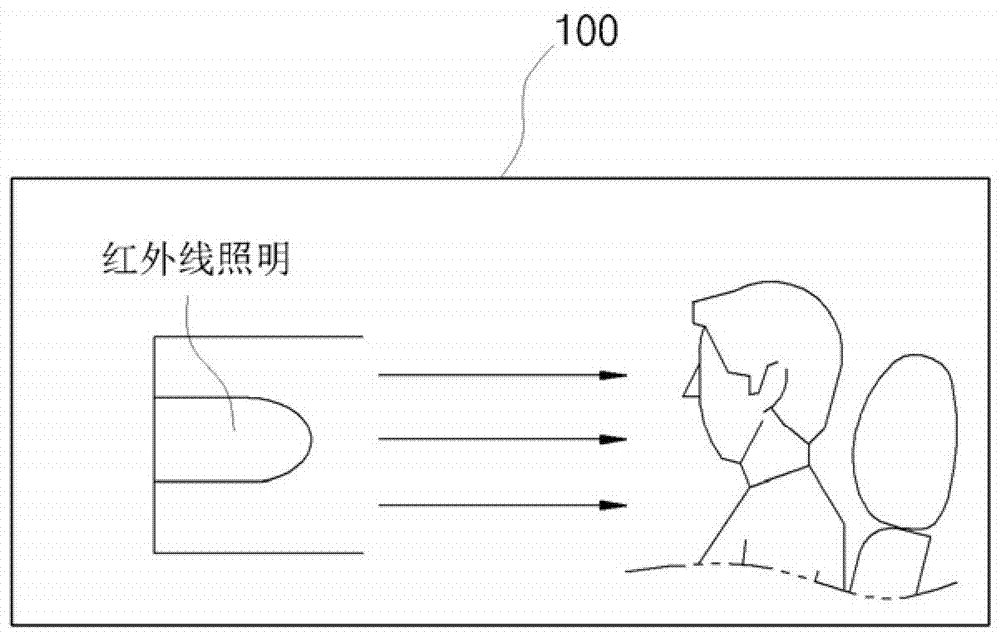
Infrared camera lighting device
An infrared camera and lighting device technology, applied in photography, camera, image communication, etc., can solve the problems of image sensor operation errors, image thermalization, etc., and achieve the effect that is not conducive to eye health
- Summary
- Abstract
- Description
- Claims
- Application Information
AI Technical Summary
Problems solved by technology
Method used
Image

Examples
Embodiment Construction
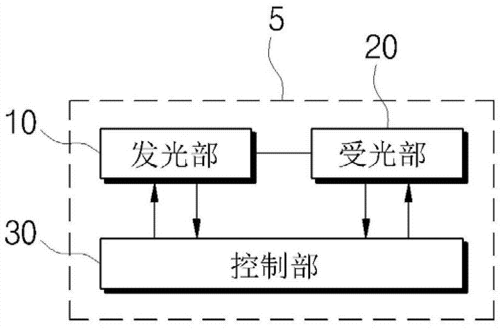
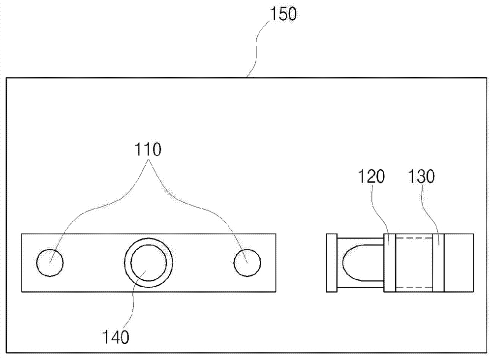
[0026] In order to make the purpose, technical solutions and advantages of the embodiments of the present invention clearer, the technical solutions in the embodiments of the present invention will be clearly and completely described below in conjunction with the drawings in the embodiments of the present invention. Obviously, the described embodiments It is a part of embodiments of the present invention, but not all embodiments. Based on the embodiments of the present invention, all other embodiments obtained by persons of ordinary skill in the art without making creative efforts belong to the protection scope of the present invention. The terms used in the present invention are only used to describe the embodiments, and not to limit the present invention. The singular form in this specification also includes the plural form unless otherwise indicated in the text. The use of "comprises" or "comprising" in the specification does not exclude the existence or existence of more ...
PUM
 Abstract
Description
Claims
Application Information