Antenna calibration method and device

An antenna calibration and reference antenna technology, which is applied in diversity/multi-antenna systems, space transmit diversity, transmission monitoring, etc., can solve problems such as long calibration time, high requirements for orthogonal calibration pilot design, and low accuracy of antenna calibration results

Active Publication Date: 2013-05-15
CHINA MOBILE COMM GRP CO LTD
View PDF4 Cites 22 Cited by
  • Summary
  • Abstract
  • Description
  • Claims
  • Application Information

AI Technical Summary

Problems solved by technology

[0019] Embodiments of the present invention provide an antenna calibration method and device, which are used to solve the problem of low accuracy of antenna calibration results between multiple cooperative base stations or RRUs in a coordinated multi-point area when the number of coordinated base stations or RRUs in the prior art is large. The problem of long calibration time and high requirements for the design of orthogonal calibration pilots

Method used


Image

  • Antenna calibration method and device
  • Antenna calibration method and device
  • Antenna calibration method and device

Examples


Embodiment 1

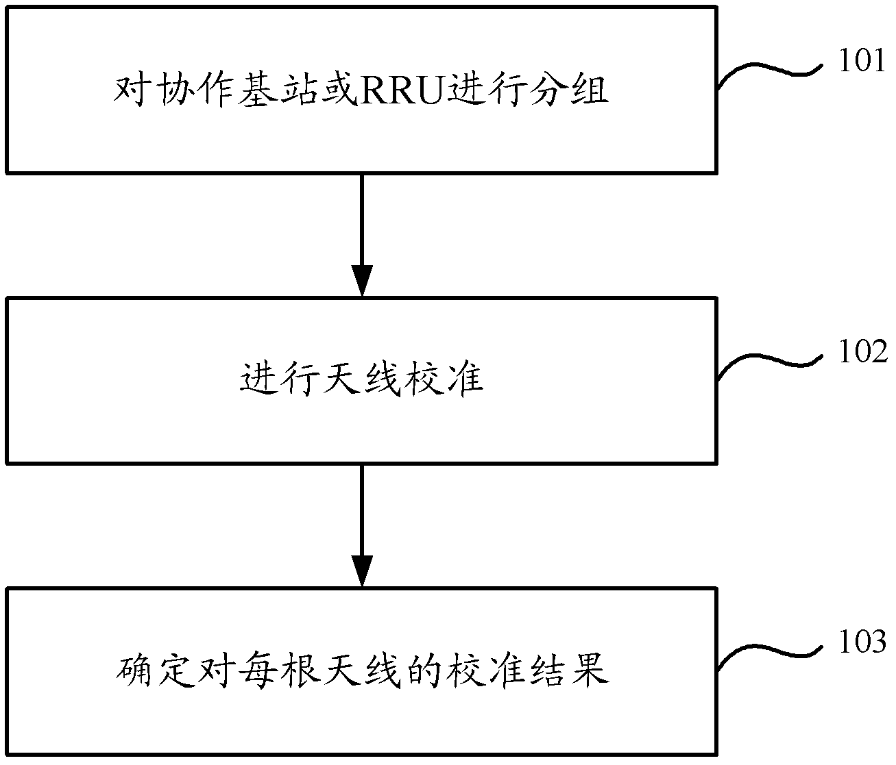
[0041] Embodiment 1 of the present invention provides an antenna calibration method, the steps of the method are as follows figure 1 shown, including:

[0042] Step 101, group the coordinated base stations or remote radio RRUs.

[0043] This step includes dividing the X coordinated base stations or remote radio RRUs in the coordinated multi-point area into Y non-overlapping groups, wherein Y is smaller than X.

[0044] Specifically, taking the grouping of coordinated base stations as an example, the coordinated base stations in the coordinated multi-point area may be grouped in the following manner:

[0045] Determining mutual calibration errors between reference antennas of any pair of coordinated base stations in a coordinated multi-point area;

[0046] Divide the coordinated base stations in the coordinated multi-point area into non-overlapping groups, each group is regarded as a first-layer equivalent base station, and in each group, the mutual relationship between the r...

Embodiment 2

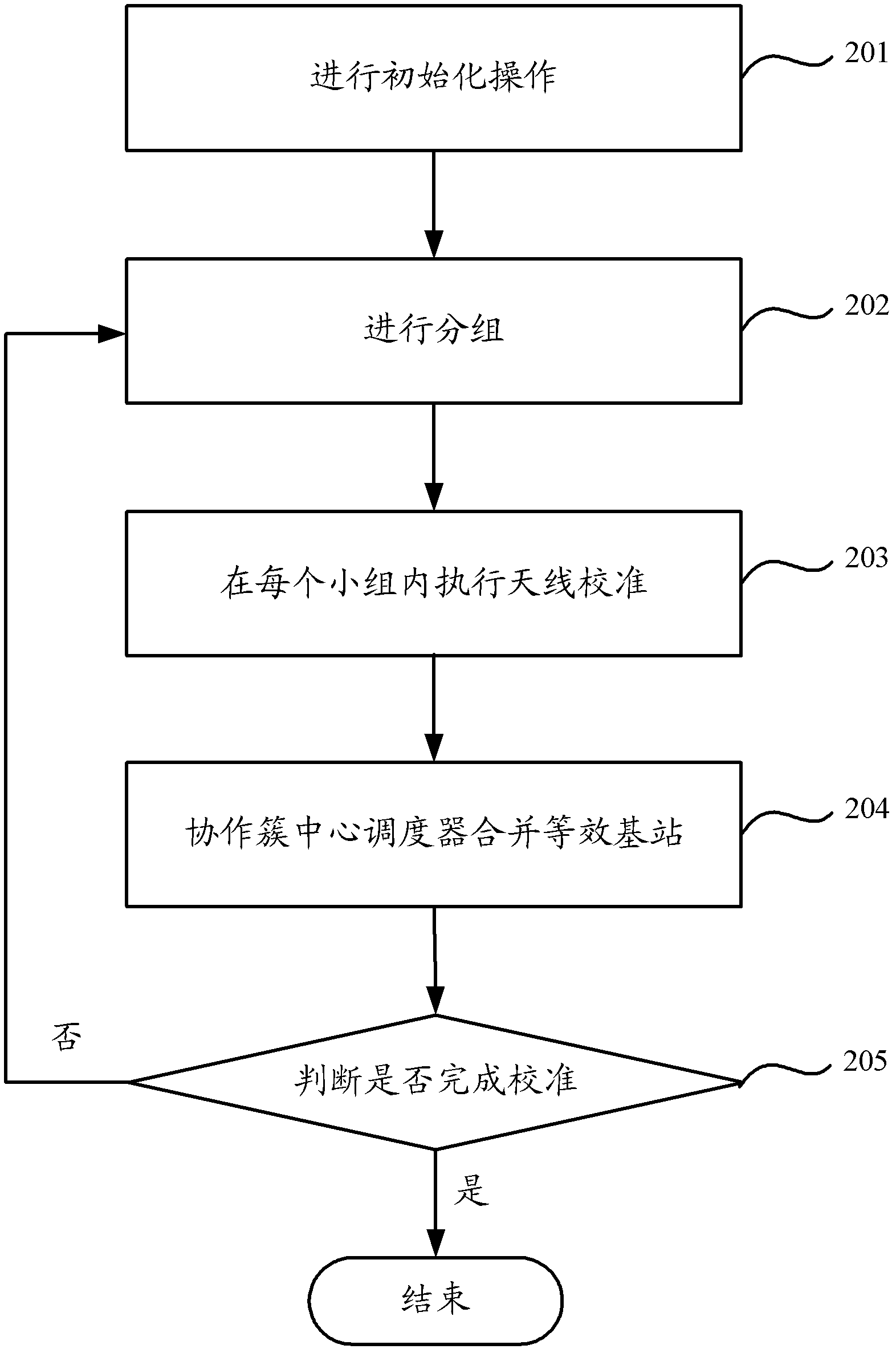
[0067] Embodiment 2 of the present invention provides an antenna calibration method, and the steps of the method are as follows figure 2 shown, including:

[0068] Step 201, perform an initialization operation.

[0069] In this embodiment, a central scheduler can be set. And the central scheduler acquires the parameter value used to represent the degree of mutual calibration error between the reference antennas of the two base stations in the coordinated multi-point area (in the coordinated cluster). Afterwards, the central scheduler can set the current calibration layer counter in this area to 1 (each base station can be regarded as an equivalent base station).

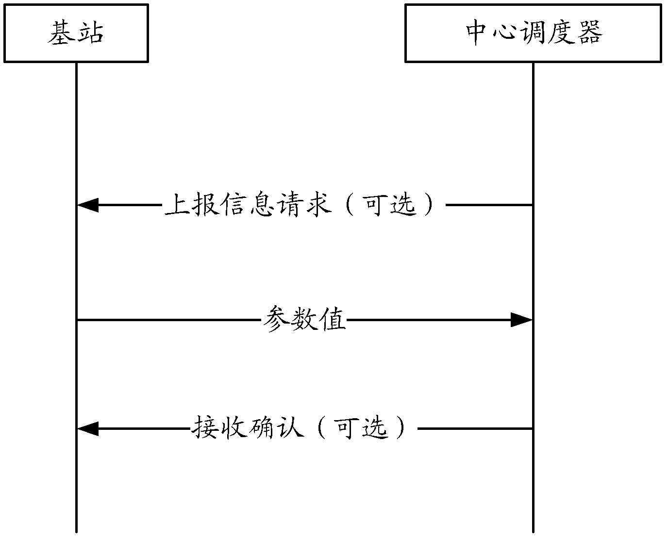
[0070] The central scheduler obtains the parameter value in the coordinated multi-point area (in the coordinated cluster), which may be that each base station periodically reports the measured or determined parameter value, or the central scheduler sends the parameter value to all base stations in the area An inf...

Embodiment 3

[0084] Embodiment 3 of the present invention provides an antenna calibration method, and the distribution of 8 RRUs in the coordinated multi-point area is as follows: Figure 8 As shown, these 8 RRUs are grouped (assuming that the set number is 3), assuming that after grouping, RRUA, RRUB and RRUC form a group, RRUD, RRUE and RRUF form a group, and RRUG and RRUH form a group. They make up the first calibration layer. Through the first calibration layer, each RRU can obtain a calibration coefficient within a group. For RRUA~RRUH, the calibration coefficients can be respectively recorded as αA1, αB1, αC1, αD1, αE1, αF1, αG1, αH1. The base stations of each group are combined to obtain three equivalent base stations, and the three equivalent base stations are marked as I, J and K respectively. Equivalent base station I, equivalent base station J and equivalent base station K are calibrated with each other to form a second calibration layer, where the calibration of equivalent bas...


PUM


Abstract

The invention provides an antenna calibration method and a device. The antenna calibration method comprises the following steps. Cooperation base stations or radio remote units (RRUs) are divided into small groups which are not mutually overlapped, the number of the small groups is smaller than that of the cooperation base stations or the RRUs, and calibration is performed on antennas in a multi-point cooperation area after grouping. Calibration results of all the antennas are confirmed so that the problems that when a large amount of cooperation base stations or RRUs in the multi-point cooperation area need to be calibrated, an existing calibration scheme not only possibly does not obtain a good calibration effect due to the fact that any empty calibration has calibration errors, but also causes long-time calibration and high demands in design of orthogonal calibration pilot frequency are solved.

Description

technical field [0001] The present invention relates to the field of wireless communication, in particular to an antenna calibration method and device. Background technique [0002] In the LTE-Advanced, Long Term Evolution-Advanced (LTE-Advanced, Long Term Evolution-Advanced) system based on same-frequency networking and using Orthogonal Frequency Division Multiple Access (OFDMA) as the access method, users at the edge of a cell will receive Signal interference severely limits the quality of service and throughput of edge users. Cooperative radio systems are a promising technique for reducing or even eliminating interference. It means that multiple base stations (or multiple remote radio frequency nodes (RRU, Radio Remote Unit)) jointly receive user signals through cooperation and combine the received signals (uplink: users transmit signals to the base station, and the base station receives signals), Or through cooperation, the user signals are weighted differently and joi...

Claims


Application Information

Patent Timeline
Patent Type & Authority Applications(China)
IPC IPC(8): H04B7/06H04B17/00H04B17/12H04B17/21
Inventor 耿健郑健金婧王启星刘建军刘光毅
Owner CHINA MOBILE COMM GRP CO LTD
Why Eureka
Try Eureka