
Energy-saving device used for air-conditioner

An energy-saving device and air-conditioning technology, applied in the field of air-conditioning, can solve problems such as the decline of heating efficiency, and achieve the effects of reducing dirty blockage, improving operation, and improving energy efficiency ratio.

Active Publication Date: 2013-05-22
HISENSE HOME APPLIANCES GRP CO LTD +1
View PDF9 Cites 0 Cited by
  • Summary
  • Abstract
  • Description
  • Claims
  • Application Information

AI Technical Summary

Problems solved by technology

The energy-saving device for air-conditioning of the present invention, by combining domestic hot water with the air inlet device, domestic hot water is placed in the water storage chamber, and the air-supply chamber can use the temperature of the hot water in the water storage chamber to condense into the air conditioner. The high temperature air is sent out by the air conditioner, so as to avoid the problem that the heating efficiency drops due to the need to turn on the electric auxiliary heating due to the low outdoor temperature when the existing air conditioner is heating.

Method used


Image

  • Energy-saving device used for air-conditioner
  • Energy-saving device used for air-conditioner
  • Energy-saving device used for air-conditioner

Examples


Embodiment 1

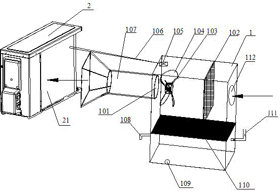
[0023] Such as figure 1 Shown is a schematic structural diagram of the energy-saving device for air-conditioning of the present invention. An energy-saving device for air-conditioning includes an air supply box 1 and a controller 105, and the air supply box is made of heat insulating boards. The air supply box includes an upper air supply chamber and a lower water storage chamber, and the air supply chamber and the water storage chamber are separated by a heat conducting metal plate 110 .

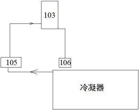
[0024] One end of the air supply chamber is provided with an air inlet 112, and the other end is provided with an air outlet 101. The air outlet 101 is connected with a telescopic air guide pipe 107, and the end of the air guide pipe 107 is connected with a trumpet-shaped flaring device. The end of the air guide pipe 107 is aligned with the air inlet 21 of the air conditioner, and a thermistor 106 for measuring the temperature at the air inlet 21 of the air conditioner is connected to the c...

Embodiment 2

[0056] This embodiment is similar to Embodiment 1, the only difference is that a heat-resistant liner and a heating device are arranged in the water storage chamber, and the heating device is electrically connected to the controller 105 . In this way, the energy-saving device of the present invention can be directly used to heat water, and tap water can be directly connected to the tap through the water inlet 111 for heating, without additional heating of a certain capacity of water and then pouring hot water into the water storage chamber. And one or more temperature sensors can be set as required to accurately control the water temperature in the water storage chamber.


PUM


Abstract

The invention relates to the technical field of air-conditioners, in particular to an energy-saving device capable of improving heating capacity of the air-conditioners. The energy-saving device is arranged at the position of an air inlet of the air-conditioner, and comprises an air supply box and a controller. The air supply box comprises an air supply chamber on the upper portion and a water storage chamber on the lower portion, and the air supply chamber and the water storage chamber are separated through a heat conducting metal plate. An air inlet is arranged at one end of the air supply chamber, an air outlet is arranged at the other end of the air supply chamber, an air fan and a filter screen are arranged in the air supply chamber and between the air inlet and the air outlet, the air fan is close to the side of the air outlet, and the filter screen is close to the side of the air inlet. The water storage chamber is provided with a water inlet and a water outlet. The air fan is driven by a motor, and the motor is in electric connection with the controller. According to the energy-saving device, the heating capacity of the air-conditioners can be greatly improved, and the energy-saving device is energy-saving and environment-friendly at the same time.

Description

technical field [0001] The invention relates to the technical field of air conditioners, and more specifically, relates to an energy-saving device capable of improving the heating capacity of the air conditioner. Background technique [0002] The heating function of the current household air conditioners is generally realized by adopting the heat exchange mode of air cooling, that is, the heat exchange form is performed by blowing the condenser with a fan. However, as the outdoor ambient temperature of the air conditioner's condenser decreases, the heat exchange effect of the condenser becomes worse and worse, resulting in lower and lower heating capacity of the air conditioner, and lower and lower energy efficiency ratio, which in turn causes the temperature in the room to not increase. The whole machine must turn on the electric auxiliary heating. But once the electric auxiliary heating is turned on, the power consumption will rise sharply, and the energy efficiency of th...

Claims


Application Information

Patent Timeline
Patent Type & Authority Applications(China)
IPC IPC(8): F24F11/02F25B29/00
Inventor 刘新华邹海如庄志宏胡鹏
Owner HISENSE HOME APPLIANCES GRP CO LTD
Learn More