Solar heating equipment

A technology of heating equipment and solar energy, which is applied in the direction of lighting and heating equipment, integration of renewable energy, heating energy from photovoltaic cells, etc. It can solve the problems that affect the efficiency of solar heating, dust and leaves are easy to adhere to, and photovoltaic panels cannot be cleaned, etc. problem, to achieve the effect of simple structure, convenient operation and reduced labor intensity

Active Publication Date: 2020-11-03
中创杰能(济宁)科技发展有限公司
View PDF14 Cites 2 Cited by
  • Summary
  • Abstract
  • Description
  • Claims
  • Application Information

AI Technical Summary

Problems solved by technology

[0006] Aiming at the deficiencies of the prior art, the present invention provides a solar heating device, which has the practicality and is simple in structure, convenient for home users to use, and does not need to manually clean the wall surface of the photovoltaic panel, which reduces the labor intensity of manual daily repair and maintenance , has the advantages of strong practicability and other advantages, and solves the problem that the photovoltaic panels and photothermal panels in the prior art are not equipped with reflective panels that can flexibly adjust the angle. The reflective panels can increase the absorption of sunlight by photovoltaic panels and photothermal panels through reflection efficiency, so as to improve the heating efficiency of solar heating equipment. Secondly, the existing public technology cannot clean the photovoltaic panels. If they are exposed to the air for a long time, dust and leaves are easy to adhere to the surface of the photovoltaic panels, resulting in a decrease in the efficiency of photovoltaic panels to absorb solar energy. problems, thus affecting the efficiency of solar heating

Method used


Image

  • Solar heating equipment
  • Solar heating equipment
  • Solar heating equipment

Examples


Embodiment Construction

[0037] The following will clearly and completely describe the technical solutions in the embodiments of the present invention with reference to the accompanying drawings in the embodiments of the present invention. Obviously, the described embodiments are only some, not all, embodiments of the present invention. Based on the embodiments of the present invention, all other embodiments obtained by persons of ordinary skill in the art without making creative efforts belong to the protection scope of the present invention.

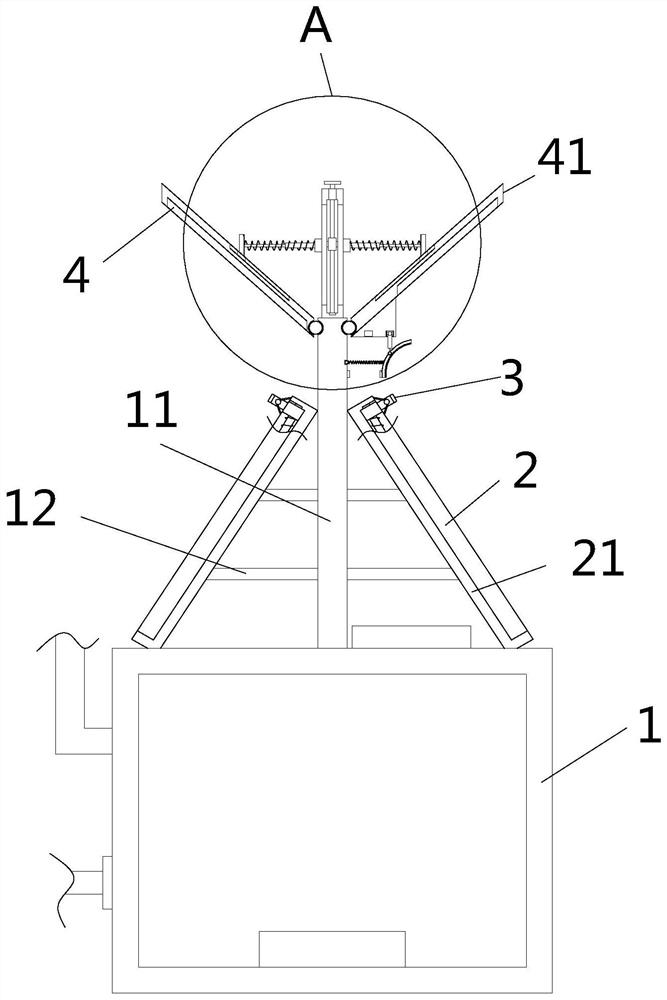
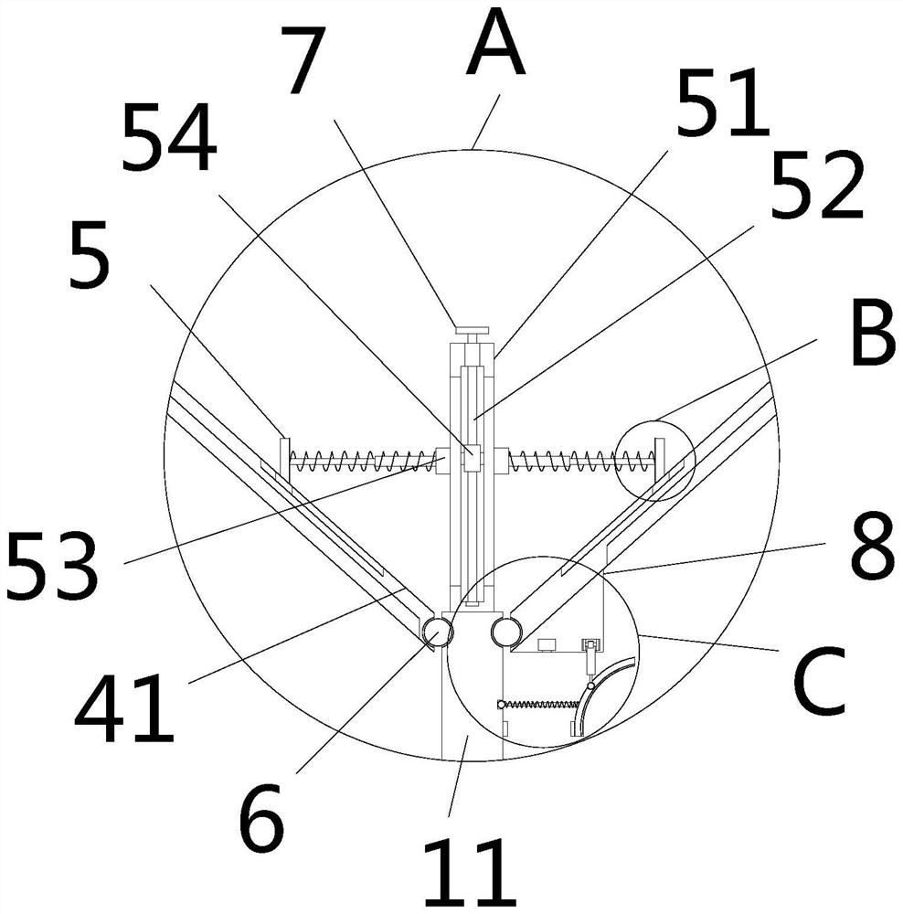
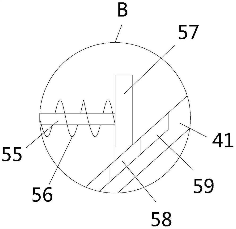
[0038] see Figure 1-11 , the present invention provides a technical solution: a solar heating equipment, including a box body 1, an electric heater is arranged in the cavity of the box body 1, and a storage battery is arranged on the top of the box body 1, and the box body 1 is a prior art, here Without going into details, a support plate 11 is fixedly installed at the center of the top of the box body 1, and crossbars 12 are fixedly installed on both sides o...


PUM


Abstract

The invention relates to the technical field of solar heating equipment, and discloses solar heating equipment which comprises a box body. A supporting plate is fixedly installed in the center of thetop of the box body, transverse rods are fixedly installed on the two sides of the supporting plate, photo-thermal plates and photovoltaic plates are arranged on the left sides and the right sides ofthe transverse rods correspondingly, and cleaning plates are fixedly installed at the right ends of the transverse rods; and cleaning devices are arranged on the two sides of the outer walls of the cleaning plates. According to the solar heating equipment, by the arrangement of the cleaning devices, cleaning frames are pulled, cleaning rods drive cleaning bristles to clean the outer walls of the photovoltaic panels, dust and adhered leaves on the outer walls of the photovoltaic panels are swept down, the condition that the dust and the leaves are adhered to the wall surfaces of the photovoltaic panels for a long time, and consequently the solar heating efficiency is low is avoided; and the cleaning devices are simple in structure and convenient for household users to use, manual cleaning of the wall surface of the photovoltaic panel is avoided, the labor intensity of manual daily repair and maintenance is reduced, and the relatively high practicability is achieved.

Description

technical field [0001] The invention relates to the technical field of solar heating equipment, in particular to a solar heating equipment. Background technique [0002] The prior art discloses a solar heating and bathing equipment (CN 209371549 U) for high-rise buildings, including photothermal panels, cabinets, photovoltaic panels, hot air equipment, shower heads, flushing nozzles and electric heaters, the cabinet The top is provided with a photothermal panel and a photovoltaic panel, and the photothermal panel and the photothermal panel are placed obliquely on the top of the box, and the photovoltaic panel and the photothermal panel are arranged symmetrically. A vertical board is fixedly installed on the top of the board, and there are two vertical boards arranged symmetrically. [0003] The existing disclosed technology uses photovoltaic panels and photothermal panels to simultaneously perform photoelectric conversion and photothermal conversion to store solar energy in...

Claims


Application Information

Patent Timeline
Patent Type & Authority Applications(China)
IPC IPC(8): F24D13/00F24D19/00H02S40/10H02S40/22B08B1/00
CPCB08B1/002F24D13/00F24D19/00F24D2200/02H02S40/10H02S40/22Y02B10/10Y02E10/52
Inventor 张丽红
Owner 中创杰能(济宁)科技发展有限公司
Why Eureka
Try Eureka