AI technical title is built by Patsnap AI team. It summarizes the technical point description of the patent document.
A composite level and level measurement technology, applied in the field of measurement, can solve the problems of low measurement efficiency and reliability, and difficulty in ensuring measurement accuracy.
Active Publication Date: 2013-05-22
DALIAN SENBIOR SURVEYING INSTR TECH CO LTD
View PDF2 Cites 19 Cited by
Summary
Abstract
Description
Claims
Application Information
AI Technical Summary
This helps you quickly interpret patents by identifying the three key elements:
Problems solved by technology
Method used
Benefits of technology
Problems solved by technology
The shortcomings are: (1) low measurement efficiency and reliability
Since the opponent's height signal measuring device uses a telescope with aiming function, an electronic telescope, an automatic leveling electronic telescope, and a compound automatic leveling electronic telescope, the composite level i The size of the angle is a key factor affecting the accuracy of the dual observation, but the above-mentioned patent application does not disclose the measurement and correction i horn, i It is difficult to guarantee the measurement accuracy due to specific measurement methods such as correction and elimination of the influence of the angle on the measured value
Method used
Image
Click on the blue label to locate the original text in one second.
Reading with bidirectional positioning of images and text.
Examples
Embodiment 1
[0068] a. Determination and calibration of the composite level before testing i horn
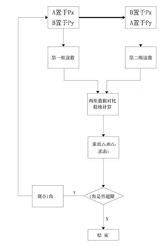
[0069] works like image 3 shown.
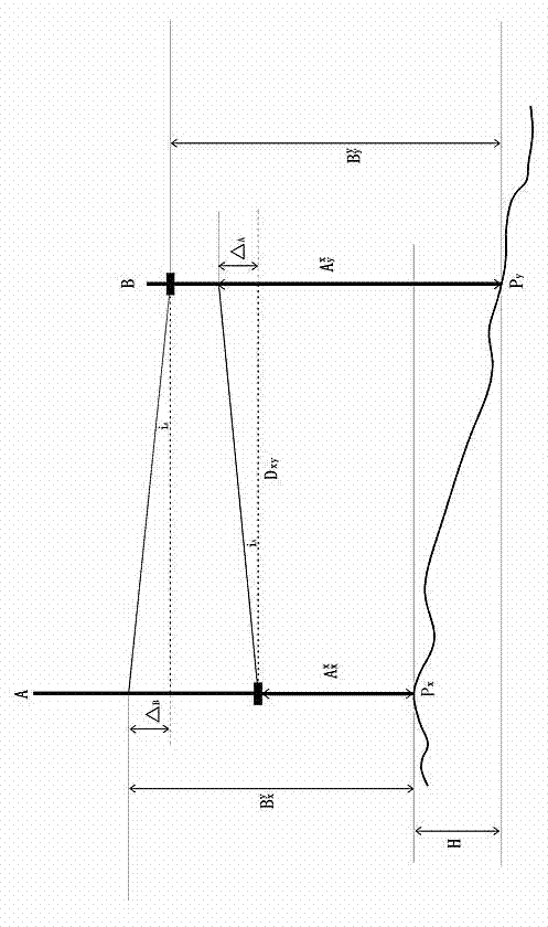
[0070] a1. If figure 1 Shown: First select two fixed points on a flat lot with , place the two composite levels A and B in with , that is, the composite level A is placed in , the compound level B is placed in , and then leveling synchronously, aiming at each other, observing and reading the local scale, and observing and reading the opposite scale, that is, measuring the fixed point as in the prior art with The first set of opponent height and own height data.
[0071] Composite level A obtained with height difference between two points It can be expressed as (Note: When calculating the height difference, the data of the other side is subtracted from the data of the other side, the same below):
[0072]
[0073] In the formula:
[0074] For composite level A i Angular error ( i When the angle is upward, it is taken as a p...
Embodiment 2
[0149] As a1, a2 steps of embodiment 1 carry out the calibration composite level before measuring i horn.
[0150] The difference from Example 1 is the b1 step. works like Figure 7 shown.
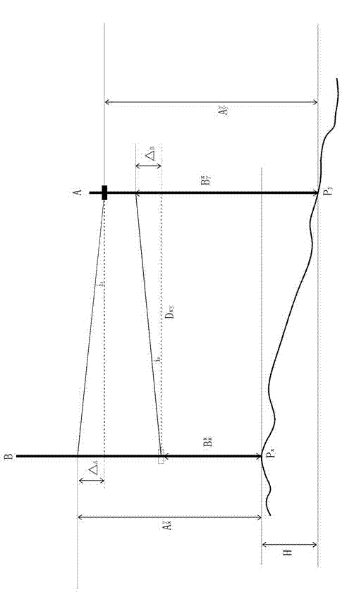
[0151] b1. Exchange placement measurement. Such as Figure 4 Shown: place the composite levels A and B respectively at the leveling points to be measured with , that is, the composite level A is placed in , the compound level B is placed in , and then leveling synchronously, aiming at each other, observing and reading the local scale, and observing and reading the opposite scale, that is, measuring the fixed point as in the prior art with The first set of opponent height and own height data.
[0152] Placed by composite level A on acquired with height difference between two points Can be expressed as:
[0153]
[0154] In the formula:
[0155] For composite level A i Angular error ( i When the angle is upward, it is taken as a positive value, i When the a...
PUM
Abstract
The invention discloses a leveling method suitable for a compound level gauge. According to the leveling method, an angle i of the compound level gauge for dual observing can be accurately measured and adjusted according to FORMULAE (details in description), so as to meet a measurement accuracy requirement; and then, steps b1, b2, b3 and b4 are carried out to carry out two-point altitude difference measurement. The steps b1, b2, b3 and b4 are as follows: b1. respectively measuring an altitude difference between Pk and Pk+1 by utilizing a compound level gauge A and a compound level gauge B; b2. calculating the difference epsilon among the altitude differences between the Pk and the Pk+1 which are measured by utilizing the compound level gauge A and the compound level gauge B; b3. judging whether the absolute value of the epsilon exceed a limit, if the absolute value of the epsilon is within a tolerance, and carrying out the step b4, and if the absolute value of the epsilon is out of tolerance, repeating the steps b1, b2 and b3; and b4, allowing the mean value of the altitude differences between the Pk and the Pk+1 which are measured by utilizing the compound level gauge A and the compound level gauge B as a measured value.
Description
technical field [0001] The invention belongs to the technical field of measurement, and in particular relates to a leveling measurement method suitable for a compound level that can ensure measurement accuracy. Background technique [0002] A traditional level measuring device is composed of a level and two leveling rods. When measuring, first place the two leveling rods on the ground at points A and B respectively, then set the level at the middle position of the two points A and B, and use the horizontal line of sight of the leveling instrument telescope to read the two points respectively. The elevation value of the leveling rod, the difference between the measured elevation values is the level difference between the two points A and B on the ground. If the elevation of one point is known, the elevation of the other point can be calculated from the height difference. In order to ensure the measurement accuracy, one is to adjust the structure of the instrument so that t...
Claims
Application Information
Patent Timeline
Application Date:The date an application was filed.
Publication Date:The date a patent or application was officially published.
First Publication Date:The earliest publication date of a patent with the same application number.
Issue Date:Publication date of the patent grant document.
PCT Entry Date:The Entry date of PCT National Phase.
Estimated Expiry Date:The statutory expiry date of a patent right according to the Patent Law, and it is the longest term of protection that the patent right can achieve without the termination of the patent right due to other reasons(Term extension factor has been taken into account ).
Invalid Date:Actual expiry date is based on effective date or publication date of legal transaction data of invalid patent.

