Illuminator failure monitoring device

A fault monitoring and illuminator technology, which is applied to lighting devices, lamp circuit layout, light sources, etc., can solve the problems of untimely maintenance, high maintenance cost, and low work efficiency, so as to improve the degree of intelligence, timely alarm at fault points, The effect of high work efficiency

Inactive Publication Date: 2013-05-22
HARBIN INST OF TECH AT WEIHAI
View PDF3 Cites 6 Cited by
  • Summary
  • Abstract
  • Description
  • Claims
  • Application Information

AI Technical Summary

Problems solved by technology

[0002] In recent years, with the growth of the economy, my country's urban lighting technology and scale have developed rapidly, but the following two traditional methods have been used in the monitoring of illuminator failures. 1. Organize special personnel to conduct regular manual inspections along the line. Manually determine the fault point; 2. According to the ratio of the current power consumption (the sum of the power consumption of the luminaires in normal working state) to the total power consumption (the sum of the total power consumption of the luminaires), the number of fault points can be estimated, but the fault cannot be determined point
[0003] The disadvantages of the above illuminator fault monitoring method are: high power consumption, low work efficiency, high maintenance cost, it is difficult for the maintenance personnel to find the illuminator fault at the first time; even if the fault is found, the type of fault cannot be quickly determined ( Such as illuminator failure, lighting controller failure or power supply line failure, etc.), often affect people's night travel safety due to untimely maintenance, and it is impossible to realize the "point-to-point" direct monitoring of illuminators by the control center

Method used


Image

  • Illuminator failure monitoring device
  • Illuminator failure monitoring device
  • Illuminator failure monitoring device

Examples


Embodiment 1

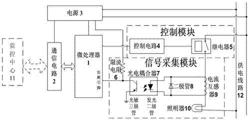
[0034] A lighting fault monitoring device, the power supply line provides 220V50Hz alternating current. As we all know, the AC current output by the current transformer 9 at this time i The change period is also 50Hz, such as Figure 5 , Figure 6 As shown by the dotted line, it will not be repeated here.

[0035] Such as figure 1 As shown, the current limiting resistor 6 is a circuit form of a pull-up resistor. When the illuminator 10 is in a normal working state, the power supply line 12 will have a current flow, and the current transformer 9 will sense and transmit an alternating current. The flow direction of the alternating current is consistent with the When the conduction directions of the light emitting diodes in the photocoupler 7 are consistent, the light emitting diodes in the photocoupler 7 will be driven to emit light and irradiate the base of the phototransistor of the photocoupler 7, and the base will be in a conduction state after being illuminated. Make th...

Embodiment 2

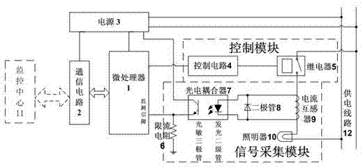
[0038] A lighting fault monitoring device, the power supply line provides 220V50Hz alternating current. As we all know, the AC current output by the current transformer 9 at this time i The change period is also 50Hz, such as Figure 6 The dotted line will not be repeated here. Such as figure 2 As shown, the current limiting resistor 6 is a circuit form of a pull-down resistor. When the illuminator 10 is in a normal working state, the power supply line 12 will have a current flow, and the current transformer 9 will sense and output an alternating current. The flow direction of the alternating current is related to the photoelectric When the conduction directions of the light-emitting diodes in the coupler 7 are consistent, the light-emitting diodes in the photocoupler 7 will be driven to emit light and irradiate the base of the phototransistor of the photocoupler 7, and the base will be in a conduction state after being illuminated, so that The level of the monitoring pin ...


PUM


Abstract

The invention relates to an illuminator failure monitoring device which comprises a microprocessor, a power source, a control module, a signal acquiring module and a communication circuit. The control module consists of a control circuit and a relay connected with the same; and the signal acquiring module consists of a current-limiting resistor, a photoelectric coupler, a diode and a current transformer. The operation principle of the illuminator failure monitoring device includes that frequency signals can be monitored by monitoring pins of the microprocessor when an illuminator runs normally, so that whether the illuminator is in failure or not can be judged. Compared with the prior art, the illuminator failure monitoring device has the advantages that functions of illuminator failure monitoring and data communication are added so that automatic monitoring and remote alarming of failure of the illuminator are realized, energy economization, real-time failure alarming, high work efficiency and low maintenance cost are achieved, and intellectualization degree of monitoring for the illuminator is increased.

Description

technical field [0001] The invention relates to a monitoring device, in particular to a lighting device fault monitoring device. Background technique [0002] In recent years, with the growth of the economy, my country's urban lighting technology and scale have developed rapidly, but the following two traditional methods have been used in the monitoring of illuminator failures. 1. Organize special personnel to conduct regular manual inspections along the line. Manually determine the fault point; 2. According to the ratio of the current power consumption (the sum of the power consumption of the luminaires in normal working state) to the total power consumption (the sum of the total power consumption of the luminaires), the number of fault points can be estimated, but the fault cannot be determined point. [0003] The disadvantages of the above illuminator fault monitoring method are: high power consumption, low work efficiency, high maintenance cost, it is difficult for the ma...

Claims


Application Information

Patent Timeline
Patent Type & Authority Applications(China)
IPC IPC(8): H05B37/03
CPCY02B20/40
Inventor 王翥佟晓筠佟少强
Owner HARBIN INST OF TECH AT WEIHAI
Why Eureka
Try Eureka