Failure monitoring device for controller of illuminator

A lighting device and fault monitoring technology, applied in lighting devices, energy-saving control technology, lamp circuit layout, etc., can solve the problems of untimely maintenance, low work efficiency, high power consumption, etc., achieve timely alarm at fault points, and improve intelligence degree, work efficiency is high

Inactive Publication Date: 2013-05-22
HARBIN INST OF TECH AT WEIHAI
View PDF3 Cites 2 Cited by
  • Summary
  • Abstract
  • Description
  • Claims
  • Application Information

AI Technical Summary

Problems solved by technology

While lighting device controllers are widely used, the monitoring of lighting device controller faults is still judged by the lighting device "on" or "not on", mainly including the following two traditional methods: 1. Organize special personnel to carry out regular inspections along the line Manual inspection, manual determination of fault points; 2. According to the ratio of current power consumption (sum of power consumption of effective lighting devices in normal analysis working state) to total power consumption (sum of total power consumption of effective lighting devices in analysis) Infer the number of failure points, but cannot determine the failure point
[0003] The disadvantages of the above lighting device controller fault monitoring method are: high power consumption, low work efficiency, high maintenance cost, it is difficult for maintenance personnel to find the fault of the lighting device controller at the first time, and even if a fault is found, it cannot be quickly judged The type of failure (such as lighting device failure, lighting device controller failure or power supply line failure, etc.), often affects the safety of night travel in the city because of untimely maintenance, let alone the "point-to-point" direct monitoring of the lighting device by the control center

Method used


Image

  • Failure monitoring device for controller of illuminator
  • Failure monitoring device for controller of illuminator
  • Failure monitoring device for controller of illuminator

Examples


Embodiment 1

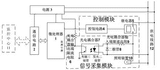
[0037] A lighting device controller failure monitoring device, the power supply line 12 provides 220V50Hz alternating current. As we all know, at this time, the working current of the lighting device 10 is an alternating current i, Alternating current i The change period is also 50Hz, such as Figure 5 , Image 6 As shown by the dotted line, it will not be repeated here.

[0038] Such as figure 1 As shown, the current-limiting resistor 6 at the output end of the photocoupler is a circuit form of a pull-up resistor. When the lighting device 10 is in a normal working state, the power supply line 12 connecting the lighting device 10 and the relay 5 will have an AC voltage, and the AC voltage is passed through the photocoupler. The current limiting resistor 9 at the input terminal of the device, the light-emitting diode in the photocoupler 7 and the diode 8 form a loop and generate an alternating current. When the flow direction of the alternating current is consistent with th...

Embodiment 2

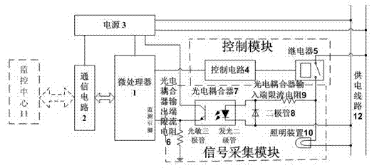
[0041] A lighting device controller failure monitoring device, the power supply line 12 provides 220V50Hz alternating current. As we all know, at this time, the working current of the lighting device 10 is an alternating current i, Alternating current i The change period is also 50Hz, such as Figure 5 , Image 6 As shown by the dotted line, it will not be repeated here.

[0042] Such as figure 2 As shown, the current-limiting resistor 6 at the output end of the photocoupler is a circuit form of a pull-down resistor. When the lighting device 10 is in a normal working state, the power supply line 12 connecting the lighting device 10 and the relay 5 will have an AC voltage, and the AC voltage will pass through the photocoupler. The input terminal current-limiting resistor 9, the light-emitting diode in the photocoupler 7, and the diode 8 form a loop and generate an alternating current. When the flow direction of the alternating current is consistent with the conduction dire...


PUM


Abstract

The invention relates to a failure monitoring device for a controller of an illuminator. The failure monitoring device comprises a microprocessor, a power source, a control module, a signal acquiring module and a communication circuit. The control module consists of a control circuit and a relay connected with the same; and the signal acquiring module consists of a photoelectric coupler, a current-limiting resistor at an input end of the photoelectric coupler, a current-limiting resistor at an output end of the photoelectric coupler and a diode. The operation principle of the failure monitoring device includes that frequency signals can be monitored by monitoring pins of the microprocessor when the controller of the illuminator runs normally, so that whether the controller of the illuminator is in failure or not can be judged. Compared with the prior art, the failure monitoring device has the advantages that functions of illuminator controller failure monitoring and data communication are added so that automatic monitoring and remote alarming of failure of the controller of the illuminator are realized, energy economization, real-time failure alarming, high work efficiency and low maintenance cost are achieved, and intellectualization degree of monitoring for the controller of the illuminator is increased.

Description

technical field [0001] The invention relates to a monitoring device, in particular to a fault monitoring device for an illuminating device controller. Background technique [0002] In recent years, with the growth of the economy, my country's urban lighting technology and scale have developed rapidly. Lighting devices are no longer just simple lighting devices. Most of them are equipped with lighting device controllers, and have electronic switches, sensors Dimming and other functions. While lighting device controllers are widely used, the monitoring of lighting device controller faults is still judged by the lighting device "on" or "not on", mainly including the following two traditional methods: 1. Organize special personnel to carry out regular inspections along the line Manual inspection, manual determination of fault points; 2. According to the ratio of current power consumption (sum of power consumption of effective lighting devices in normal analysis working state) to...

Claims


Application Information

Patent Timeline
Patent Type & Authority Applications(China)
IPC IPC(8): H05B37/03
CPCY02B20/48Y02B20/40
Inventor 王翥佟晓筠佟少强
Owner HARBIN INST OF TECH AT WEIHAI
Why Eureka
Try Eureka