Rail wagon bearing seal cover removing machine

A technology of bearing sealing and cover pulling machine, which is applied in the direction of metal processing, metal processing equipment, manufacturing tools, etc., can solve the problems of low work efficiency and high labor intensity of operation, and achieve the improvement of work efficiency, reduction of labor intensity, structural design reasonable effect

Inactive Publication Date: 2013-06-05
HARBIN YIXING TECH DEV
View PDF6 Cites 9 Cited by
  • Summary
  • Abstract
  • Description
  • Claims
  • Application Information

AI Technical Summary

Problems solved by technology

[0003] The purpose of the present invention is to solve the problems of high labor intensity, low work efficiency and inability to meet the requirements of high-speed development of railway operation and modernization management of railways in order to solve the problems that manual operation is used to remove the bearing seal cover of railway freight car bearings, and further provide a Pulling machine for bearing seal cover of railway wagon

Method used


Image

  • Rail wagon bearing seal cover removing machine
  • Rail wagon bearing seal cover removing machine
  • Rail wagon bearing seal cover removing machine

Examples


specific Embodiment approach 1

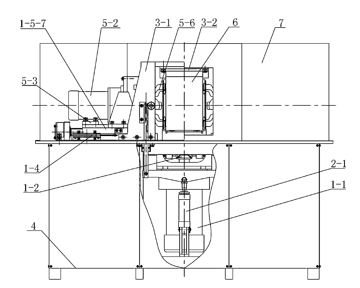
[0009] Specific implementation mode one: combine Figure 1-Figure 10 Describe this embodiment mode, a kind of machine that pulls out the sealing cover of railway freight car bearing in this embodiment mode comprises transmission device 1, ejection mechanism 2, fixing device 3, frame 4 and two sets of cover pulling mechanisms 5;

[0010] The transmission device 1 includes a first motor 1-1, a first bevel gear 1-2, two second bevel gears 1-3, two first electronic rulers 1-4 and two sets of drive mechanisms 1-5, the first A motor 1-1 is installed on the frame 4, the output shaft of the first motor 1-1 is vertically arranged, the first bevel gear 1-2 is fixedly installed on the output shaft of the first motor 1-1, two second The bevel gear 1-3 is arranged on both sides of the axis of the first bevel gear 1-2, and the two second bevel gears 1-3 are meshed with the first bevel gear 1-2. The two sets of driving mechanisms 1 -5 is directly arranged on both sides of the axis of the fi...

specific Embodiment approach 2

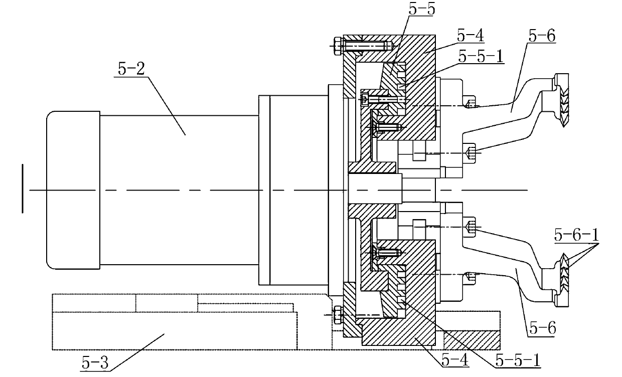
[0013] Specific implementation mode two: combination Figure 5 To illustrate this embodiment, each set of drive mechanism 1-5 in this embodiment includes a shaft rod 1-5-1, a first gear 1-5-2, a second gear 1-5-3, a lead screw 1-5- 4. The screw seat 1-5-5, the guide rail 1-5-6 and the slider 1-5-7, the shaft 1-5-1 is set horizontally, and the second cone is installed at one end of the shaft 1-5-1 Gear 1-3, the other end of the shaft rod 1-5-1 is equipped with a first gear 1-5-2, the first gear 1-5-2 meshes with the second gear 1-5-3, the second gear 1-5-2 5-3 is installed on the lead screw 1-5-4, and the lead screw 1-5-4 is installed on the lead screw seat 1-5-5 and the two are connected in rotation, and one end of the slider 1-5-7 is connected to the lead screw 1-5-4 thread connection, the other end of the slider 1-5-7 is installed on the guide rail 1-5-6, and the slider 1-5-7 can slide horizontally on the guide rail 1-5-6, the guide rail 1 -5-6 is installed on the upper su...

specific Embodiment approach 3

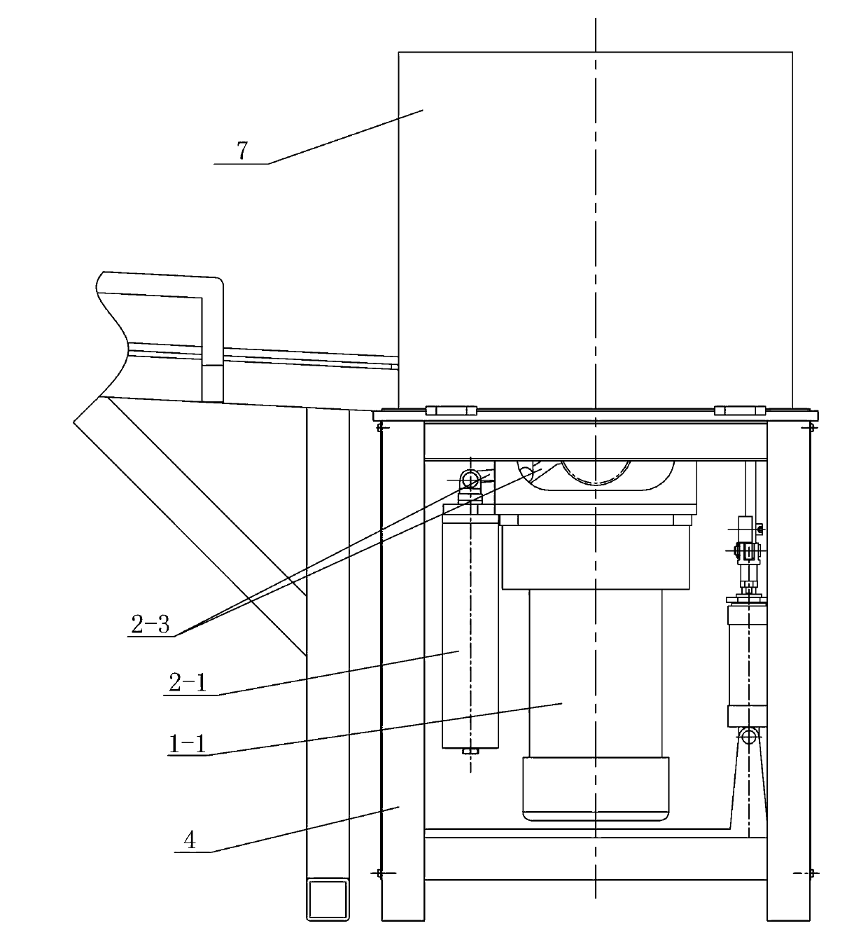
[0014] Specific implementation mode three: combination Figure 6 and Figure 7 To illustrate this embodiment, the ejector mechanism 2 in this embodiment includes a first cylinder 2-1, a cylinder bracket 2-2, a lever 2-3, a push rod 2-4, a top plate 2-5 and a lower tire block 2-6 , the cylinder bracket 2-2 is installed on the frame 4, the first cylinder 2-1 is installed on the cylinder bracket 2-2, the end of the driving rod of the first cylinder 2-1 is hinged with one end of the lever 2-3, and the lever The other end of 2-3 is hinged with the cylinder bracket 2-2, the lower tire block 2-6 is installed on the upper surface of the frame 4, the top plate 2-5 is rotationally connected with the lower tire block 2-6, and the push rod 2-4 One end is rotatably connected with the top plate 2-5, the other end of the push rod 2-4 is rotatably connected with the lever 2-3, the lower tire block 2-6 is used for supporting the bearing, and the top plate 2-5 is used for ejecting the bearing....


PUM


Abstract

The invention discloses a rail wagon bearing seal cover removing machine and relates to bearing seal cover removing equipment. The rail wagon bearing seal cover removing machine solves the problems that due to the fact that a bearing seal cover of a rail wagon bearing is removed manually, labor intensity of operation is large, working efficiency is low and requirements of rapid development of railway operation and modernization management of railways can not be met. The rail wagon bearing seal cover removing machine comprises a transmission device, an ejection mechanism, a fixing device, a machine frame, and two cover removing mechanisms. The transmission device comprises a first motor, a first bevel gear, two second bevel gears, two first electronic rulers and two driving mechanisms. The first motor is installed on the machine frame. The two bevel gears are respectively connected with a driving mechanism. Each driving mechanism is provided with one electronic ruler. Each cover removing mechanism comprises a second electronic ruler, a second motor, a base seat, a chuck body, a disc and four clamp jaws. The ejection mechanism is arranged on the machine frame. The fixing device is installed on the machine frame. The rail wagon bearing seal cover removing machine is used for removal of rail wagon bearing seal covers.

Description

technical field [0001] The invention relates to a device for removing a bearing sealing cover, in particular to a device for removing a bearing sealing cover on a railway wagon. Background technique [0002] Due to the special structure of the end face sealing cover of railway freight car bearings, during the process of overhaul, overhaul and testing, only simple tooling and tools can be used to manually pull out the cover. The strength is high, the efficiency is very low, it cannot be automated, and it cannot meet the requirements of the rapid development of railway operation and the modernization of railway management. Contents of the invention [0003] The purpose of the present invention is to solve the problems of high labor intensity, low work efficiency and inability to meet the requirements of high-speed development of railway operation and modernization management of railways in order to solve the problems that manual operation is used to remove the bearing seal c...

Claims


Application Information

Patent Timeline
Patent Type & Authority Applications(China)
IPC IPC(8): B23P19/00
Inventor 李冰王臣业李晶董丽红
Owner HARBIN YIXING TECH DEV
Why Eureka
Try Eureka