Method and system for compensating engine thermal conditions

A technology of engine and engine temperature, which is applied in the direction of combustion engine, engine control, machine/engine, etc. It can solve problems such as valve expansion or contraction, valve event changes, etc., and achieve the effects of reducing vehicle emissions, increasing engine emissions, and reducing engine misfires

Active Publication Date: 2013-06-05
FORD GLOBAL TECH LLC
View PDF5 Cites 0 Cited by
  • Summary
  • Abstract
  • Description
  • Claims
  • Application Information

AI Technical Summary

Problems solved by technology

In this way, DAMB-operated valves can respond quickly, however, temperature changes that occur in an engine with DAMB-operated valves may cause expansion or contraction of the valves resulting in changes in valve event timing

Method used


Image

  • Method and system for compensating engine thermal conditions
  • Method and system for compensating engine thermal conditions
  • Method and system for compensating engine thermal conditions

Examples


Embodiment Construction

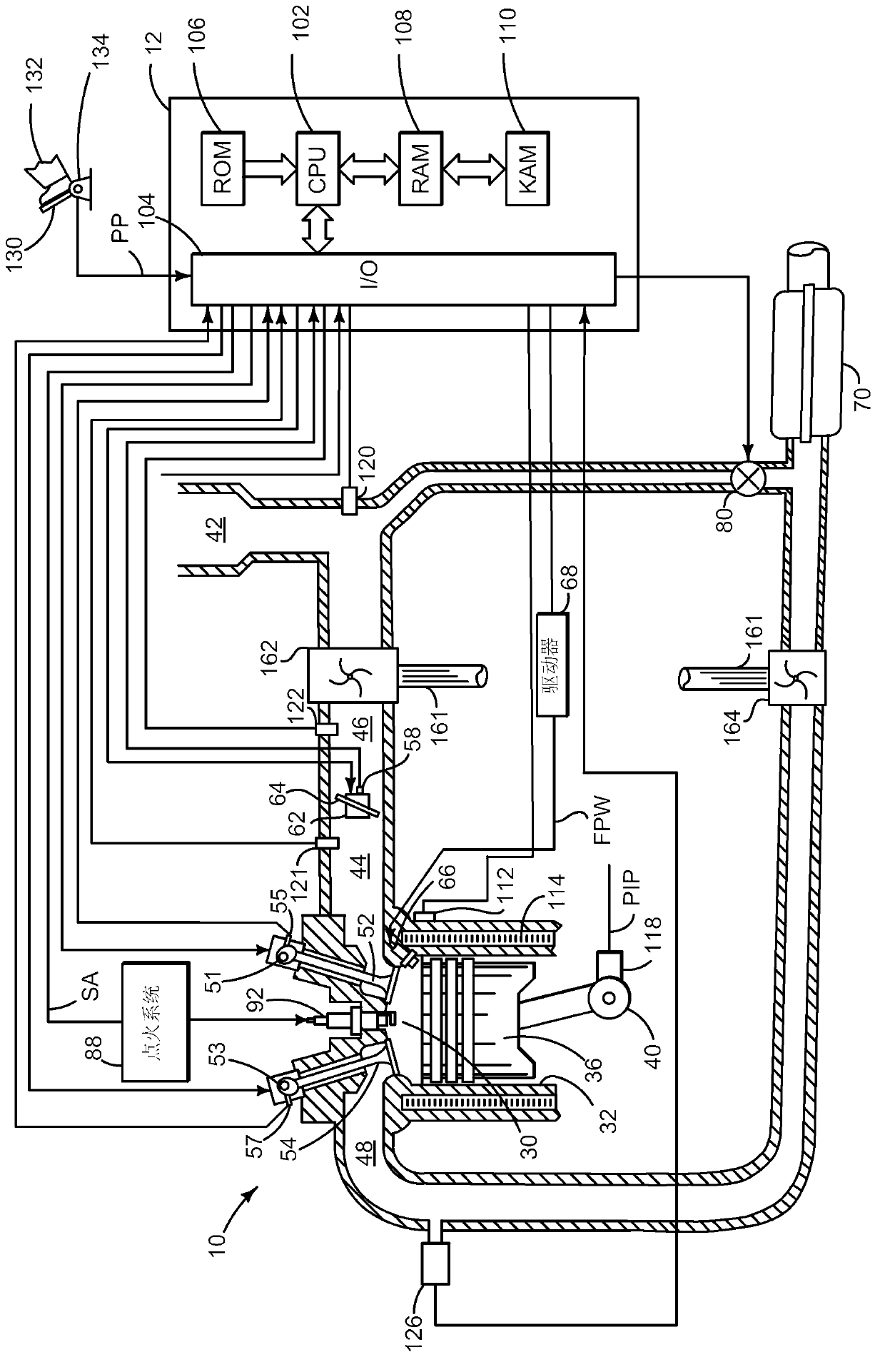
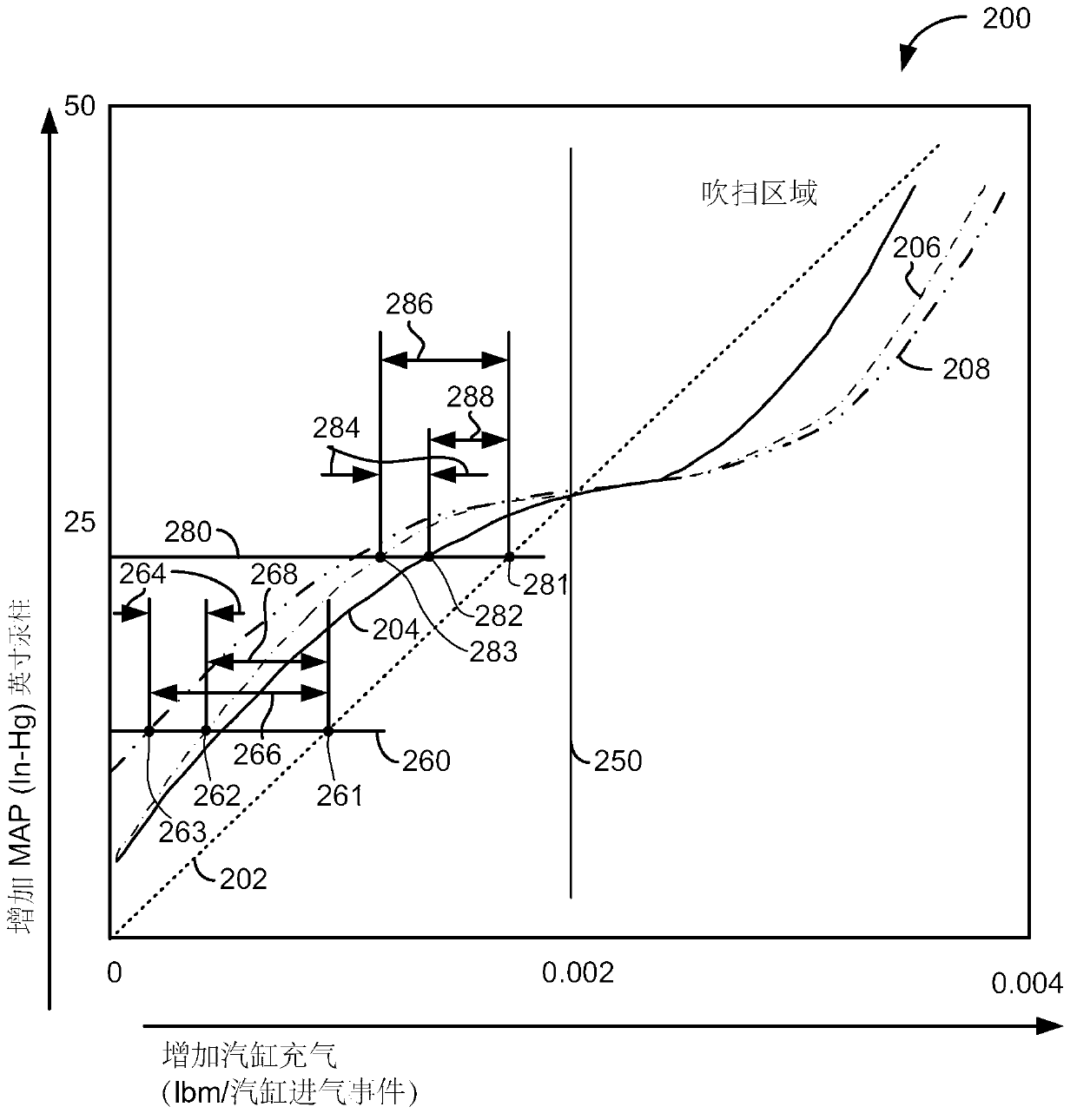
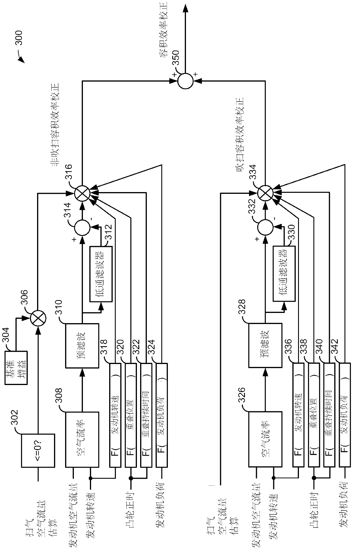
[0014] The present invention relates to regulating the amount of cylinder air and the amount of residual gas in the cylinders of an engine. figure 1 An example system for regulating cylinder air volume of cylinders is shown. In some examples, the system may include a turbocharger and a spark ignited mixture of air and gasoline, alcohol, or gasoline and alcohol. However, in other examples, the engine may be a compression ignition engine, such as a diesel engine. figure 2 An example graph of the simulation is shown, which is the basis for compensating the cylinder air volume and cylinder residual volume. image 3 An example method for adjusting cylinder air volume is shown. exist Figure 4-5 A visual example of how to adjust cylinder air mass, MAP, and cylinder residual mass according to the method described here is shown in . exist Figure 6 A flow diagram of a method for adjusting a cylinder air quantity and a cylinder residual gas quantity is shown in .

[0015] now re...


PUM


Abstract

A method for compensating for thermal transient conditions of an engine that can cause valve growth or contraction is disclosed. In one example, the method provides cylinder air amount compensation during non-blow-through and blow-through conditions. The approach may improve cylinder air amount estimates, thereby improving engine emissions.

Description

【Technical field】 [0001] The present invention relates to regulating the amount of cylinder air and the amount of residual gas in the cylinders of an engine. 【Background technique】 [0002] Directly Linked Mechanical Bucket (DAMB) valve actuators can be manufactured without valve lash adjustment. As such, DAMB-operated valves may respond quickly, however, temperature changes occurring in an engine with DAMB-operated valves may cause expansion or contraction of the valves resulting in variations in valve event timing. For example, changes in engine load can cause engine temperature and pressure to rise. Increased cylinder temperature may cause the exhaust valve to expand. In addition, the cylinder head may also expand, and the exhaust valve expansion rate may be different from the cylinder head expansion rate because the exhaust valve and cylinder head may be formed of different materials or because the cooling for the exhaust valve and cylinder head is different. Temperat...

Claims


Application Information

Patent Timeline
IPC IPC(8): F02D45/00
CPCF02D11/105F02D41/00F02D2041/1422F02D41/0007F02D2041/001F02D2200/0406Y02T10/144F02D2200/0411F02D2200/0408F02D41/182F02D2041/1432F02D37/02F02D2200/101Y02T10/12
Inventor D·G·海格纳M·J·扬科维奇M·W·弗里德
Owner FORD GLOBAL TECH LLC
Why Eureka
Try Eureka