Method for improving transient engine operation

a transient engine and fuel control technology, applied in the direction of machines/engines, process and machine control, combustion air/fuel air treatment, etc., can solve the problems of poor combustion stability, poor drivability and/or increasing engine emissions, and engine emissions reduction, so as to improve fuel economy, reduce engine pumping work and cylinder combustion temperature, and improve engine performan

Active Publication Date: 2011-06-09
FORD GLOBAL TECH LLC
View PDF61 Cites 30 Cited by
  • Summary
  • Abstract
  • Description
  • Claims
  • Application Information

AI Technical Summary

Benefits of technology

[0002]An engine may be operated with charge dilution to lower engine emissions and improve fuel economy. Charge dilution can reduce engine pumping work and cylinder combustion temperature, thereby improving engine operation. However, if an engine is operated at a high level of charge dilution and there is a rapid change in operating conditions (e.g., a change in engine load), the engine may suffer poor combustion stability and / or misfire, thereby causing poor drivability and / or increasing engine emissions.
[0004]By increasing injection of a gaseous fuel during a transient engine operating condition it may be possible to reduce engine misfires when the engine is operating at a higher dilution level. Further, an engine may be operated at higher dilution levels to improve fuel economy and emissions, at least under some conditions, when combustion stability can be improved during transient engine operating conditions. Increasing combustion stability can reduce the possibility of poor combustion stability and / or engine misfires, thereby improving drivability and / or decreasing engine emissions.
[0005]The present description may provide several advantages. Specifically, the approach may allow an engine to operate at higher charge dilution levels. As such, engine efficiency may be improved by the following method. Further, the method may reduce engine emissions during transient operating conditions.

Problems solved by technology

However, if an engine is operated at a high level of charge dilution and there is a rapid change in operating conditions (e.g., a change in engine load), the engine may suffer poor combustion stability and / or misfire, thereby causing poor drivability and / or increasing engine emissions.
Further, the method may reduce engine emissions during transient operating conditions.

Method used


Image

  • Method for improving transient engine operation
  • Method for improving transient engine operation
  • Method for improving transient engine operation

Examples


Embodiment Construction

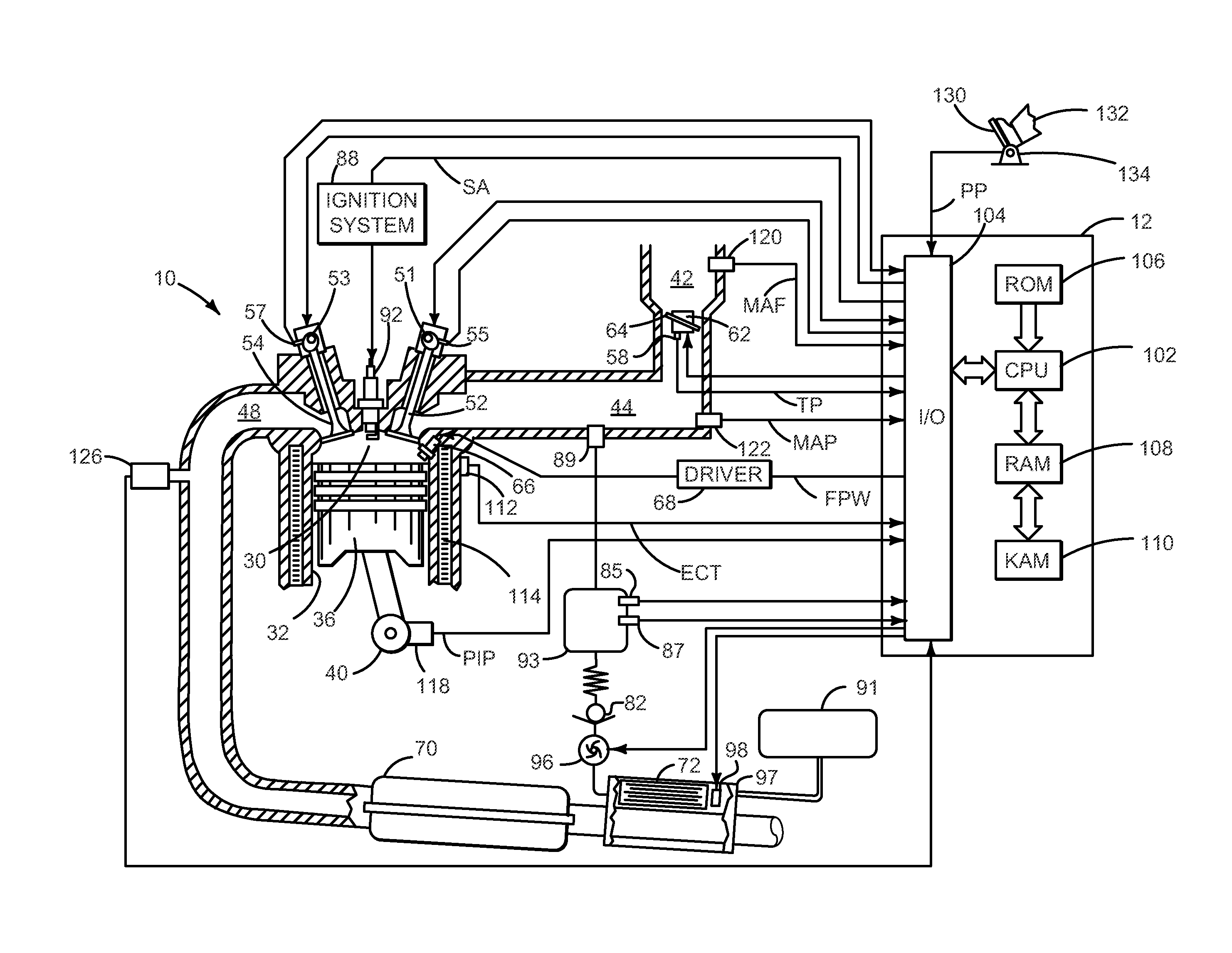
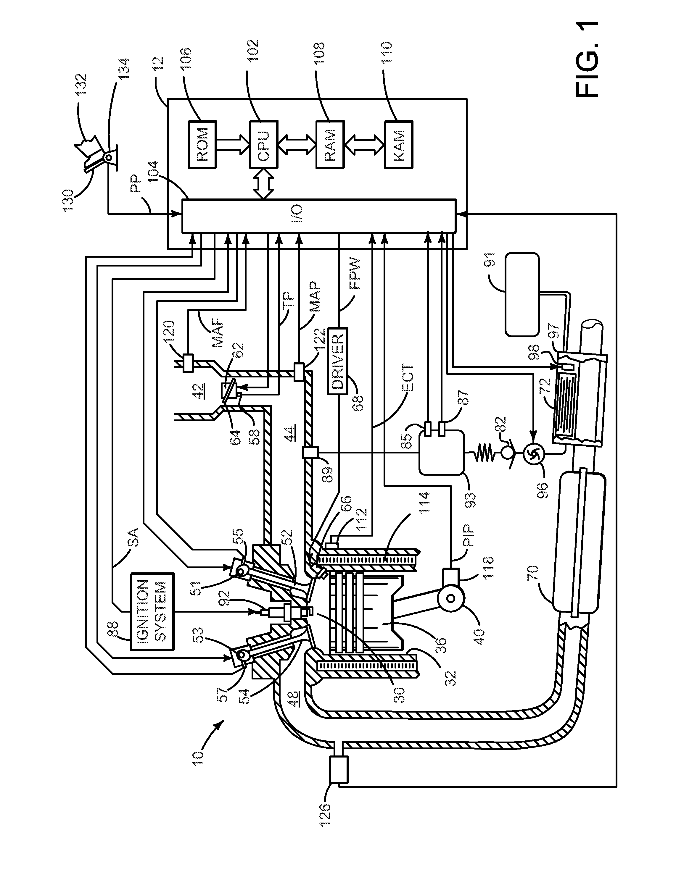
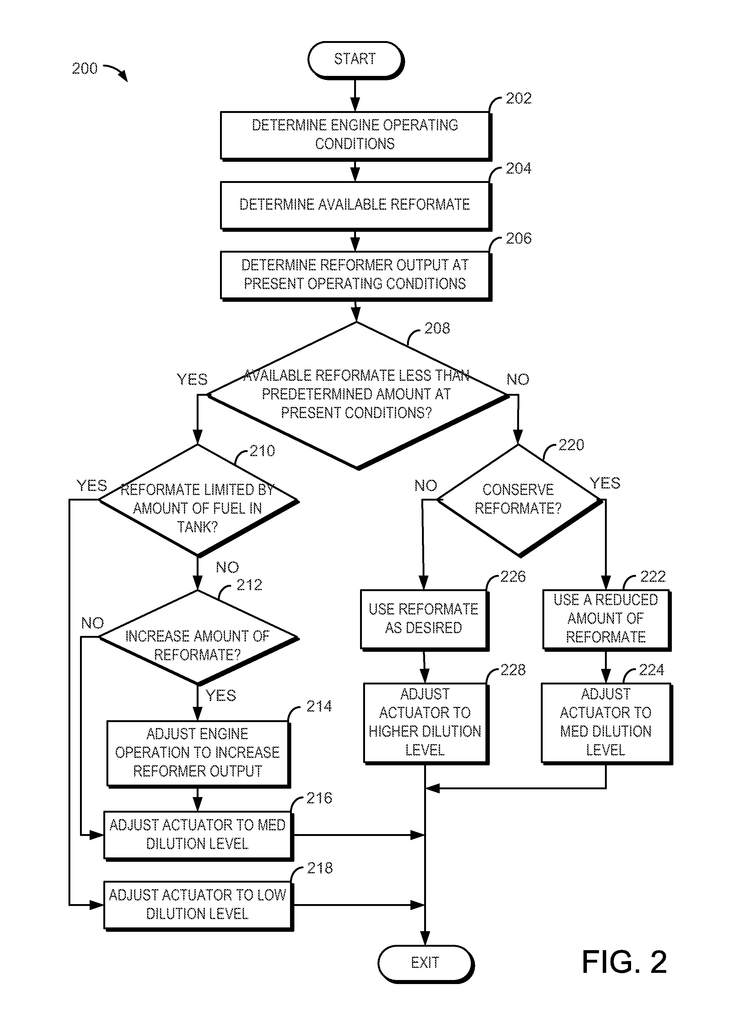
[0020]The present description is related to operating an engine with a fuel reformer. In one embodiment, the engine may be configured with variable valve timing and spark ignition as is illustrated in FIG. 1. The fuel reformer may allow the engine to operate with higher charge dilution (e.g., leaner or with additional EGR) and with higher density cylinder mixtures. FIGS. 2 and 3 show routines of example dilution and knock control routines that may be used to take advantage of reformate produced by the fuel reformer. FIGS. 4 and 5 show example engine operating regions and signals of interest when operating an engine with reformate. FIGS. 6-9 show example routines and engine air-fuel signals of interest when operating an engine with reformate. FIGS. 10-11 show an example routine and engine signals of interest when prioritizing reformate use for improving operation of an engine and conserving reformate.

[0021]Referring to FIG. 1, internal combustion engine 10, comprising a plurality of ...


PUM


Abstract

A method for operating an engine with a fuel reformer is presented. In one embodiment a method for operating an engine by injecting a gaseous fuel and a liquid fuel to at least an engine cylinder is presented. The mixture of an engine cylinder may be diluted with EGR and a fraction of gaseous fuel may be increased relative to a fraction of liquid fuel injected to a cylinder in response to an operator tip-out.

Description

FIELD[0001]The present description relates to a method for improving fuel control of an engine. The method may be particularly useful for controlling fuel to an engine that may operate using two fuels.BACKGROUND AND SUMMARY[0002]An engine may be operated with charge dilution to lower engine emissions and improve fuel economy. Charge dilution can reduce engine pumping work and cylinder combustion temperature, thereby improving engine operation. However, if an engine is operated at a high level of charge dilution and there is a rapid change in operating conditions (e.g., a change in engine load), the engine may suffer poor combustion stability and / or misfire, thereby causing poor drivability and / or increasing engine emissions.[0003]The inventors herein have recognized the above-mentioned disadvantages and have developed a method for improving engine operation during transient operating conditions. One embodiment of the present description includes a method for operating an engine, com...

Claims


Application Information

Patent Timeline
Patent Type & Authority Applications(United States)
IPC IPC(8): F02P5/04F02M21/02F02M25/07F01L1/34F02D41/30
CPCY02T10/36Y02T10/126F02B2075/125F02D13/0207F02D13/0219F02D19/0644F02D19/0671F02D19/0692F02D19/081F02D41/0025F02D41/0027F02D41/3064F02D41/3094F02M27/02F02M31/18F02P5/1527Y02T10/123Y02T10/46Y02T10/12Y02T10/30Y02T10/40
Inventor SURNILLA, GOPICHANDRALEONE, THOMAS G.
Owner FORD GLOBAL TECH LLC
Why Eureka
Try Eureka