Pipe rotation limiting device

A technology of rotation constraints and pipelines, which is applied in the direction of pipeline brackets, pipes/pipe joints/fittings, mechanical equipment, etc., and can solve problems such as installation space restrictions

Active Publication Date: 2015-06-17
CHINA INSTITUTE OF ATOMIC ENERGY
View PDF5 Cites 0 Cited by
  • Summary
  • Abstract
  • Description
  • Claims
  • Application Information

AI Technical Summary

Problems solved by technology

However, due to the limitation of installation space, it cannot be realized by adding a conventional translation bracket, but a device that directly constrains the rotation of the pipeline is required
And there is no pipeline rotation restraint device that can realize the above-mentioned function in the prior art

Method used


Image

  • Pipe rotation limiting device
  • Pipe rotation limiting device

Examples


Embodiment 1

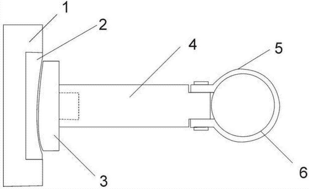
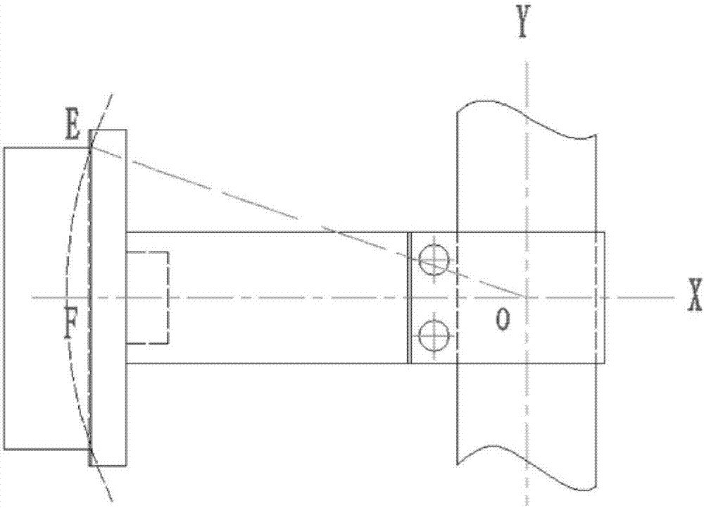
[0029] Pipe rotation restraint device, the device is mainly composed of baffle plate 1, concave arc insert 2, convex arc insert 3 and T-beam 4, wherein the concave arc The insert is clamped into the T-beam 4 by the expansion joint process, one end of the T-beam 4 is fastened to the pipe 6 through the clamp 5, and the convex arc insert 3 at the other end is put into the arc groove of the concave arc insert 2, and the convex The convex arc surface of the arc insert 3 and the concave arc surface of the concave arc insert 2 are both concentric cylindrical surfaces with the center of the pipe as the center, and the convex and concave arc surfaces coincide. The baffle 1 is fastened to the ground or the wall by using bolts or welding. The materials of the baffle plate 1, the concave arc insert 2, the convex arc insert 3, the T-beam 4 and the clip 5 are all stainless steel. Both the convex arc insert 3 and the concave arc insert 2 are quenched and hardened to increase wear resistance...

Embodiment 2

[0035] The difference from Embodiment 1 is that two sets of pipeline restraint devices are used and installed in two directions orthogonal to each other, so that the function of restraining two torques can be realized.


PUM


Abstract

The invention belongs to the field of pipe limiting, and discloses a pipe rotation limiting device. The pipe rotation limiting device is mainly composed of a baffle (1), a concave arc insert (2), a convex arc insert (3) and a T-type beam (4), wherein the concave arc insert (2) is clamped into the baffle (1) through adoption of an expansion connection technology, the convex arc insert is clamped into the T-type beam (4) through the adoption of the expansion connection technology, one end of the T-type beam (4) is fastened with a pipe (6) through a clamping hoop (5), the convex arc insert (3) at the other end of the T-type beam (4) is placed in an arc chute formed in the concave arc insert (2), a convex arc face of the convex arc insert (3) and a concave arc face of the concave arc insert (2) are both concentric cylinder faces with the pipe center as the circle centers, and the convex arc face is matched with the concave arc face. The pipe rotation limiting device is a device which directly limits the pipe rotation without limiting the pipe translational motion.

Description

technical field [0001] The invention belongs to the technical field of pipeline restraint, and in particular relates to a pipeline rotation restraint device. Background technique [0002] The piping system of a large reactor is often very large. The pipeline is tens of meters long and hundreds or even thousands of millimeters in diameter. It often spans several workshops and connects important equipment such as main pumps and heat exchangers. It must bear the combined effects of temperature, pressure, vibration and other loads. The stress analysis of the pipeline system is to reasonably configure supports and hangers on the pipeline to limit the displacement of the pipeline so that the stress meets the relevant requirements of the code. [0003] In three-dimensional space, piping nodes have six degrees of freedom, namely three linear displacements and three angular displacements. So far, the pipe supports and hangers used in engineering, except that the fixed frame restric...

Claims


Application Information

Patent Timeline
Patent Type & Authority Patents(China)
IPC IPC(8): F16L3/08
Inventor 戴守通
Owner CHINA INSTITUTE OF ATOMIC ENERGY
Why Eureka
Try Eureka