Tension-free cable layover device
A tension-free and cable-free technology, applied in the direction of overhead lines/cable equipment, etc., can solve problems such as time-consuming, difficult, and high construction costs, and achieve the effects of low construction cost, reduced production cost, and improved construction quality
- Summary
- Abstract
- Description
- Claims
- Application Information
AI Technical Summary
Problems solved by technology
Method used
Image
Examples
Embodiment 1
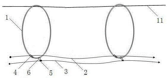
[0027] Such as figure 1 and figure 2 The shown tension-free cable release spanning device includes an elastic insulating rod 1, a cable guide rope 2 and a series traction rope 3. The material of the elastic insulating rod 1 is an insulating elastic glass fiber reinforced plastic composite material. metal joint 4, the elastic insulating rod 1 is butted through the metal joint 4 to form an elastic insulating ring, the cable guiding rope 2 passes through the elastic insulating ring, and the connecting ring 5 at intervals is fixed on the series traction rope 3, the The connecting ring 5 is fixedly connected with the elastic insulating ring through the hanging buckle 6 .
[0028] The above-mentioned elastic insulating rod 1 is made of insulating elastic fiberglass composite material.
[0029] Such as Figure 5 As shown, the buckle 6 is a gourd-shaped carabiner, including a hook 61 and an elastic push rod 63. The connecting end of the hook 61 and the elastic push rod 63 is provi...
Embodiment 2
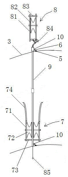
[0032] Such as image 3 The shown tension-free cable laying and spanning device includes an insulating pulley, a cable guiding rope 2 and a series traction rope 3, the cable guiding rope 2 is slidably connected to the guide pulley 7 of the insulating tackle, and the series pulling rope 3 is connected to the insulating pulley. The insulating connecting rod 9 of the pulley is connected; the insulating block also includes a traveling pulley 8 and a hollow insulating connecting rod 9, the upper end of the insulating connecting rod 9 is connected with the traveling pulley 8, and the lower part is connected with the guide pulley 7, and the upper end of the insulating connecting rod 9 , and the lower two ends are respectively provided with fixed rings 10, and the series traction rope 3 is connected with the fixed rings 10.
[0033] Such as image 3 As shown, the walking pulley 8 includes two vertical A splints 81 parallel to each other, and a first pulley 82 arranged between the A s...
PUM
 Abstract
Description
Claims
Application Information
 - R&D
- Intellectual Property
- Life Sciences
- Materials
- Tech Scout
- Unparalleled Data Quality
- Higher Quality Content
- 60% Fewer Hallucinations
Browse by: Latest US Patents, China's latest patents, Technical Efficacy Thesaurus, Application Domain, Technology Topic, Popular Technical Reports.
© 2025 PatSnap. All rights reserved.Legal|Privacy policy|Modern Slavery Act Transparency Statement|Sitemap|About US| Contact US: help@patsnap.com


