Straight twisting machine

A technology of direct twisting machine and frame, applied in spinning machine, spinning machine with continuous winding, textile and paper making, etc., can solve the problems that the balloon shape cannot be optimal, and the tension control of outer yarn cannot be accurately controlled. , to achieve the effect of saving energy consumption and reducing noise

Inactive Publication Date: 2013-06-12
ZHEJIANG RIFA TEXTILE MASCH CO LTD
View PDF6 Cites 5 Cited by
  • Summary
  • Abstract
  • Description
  • Claims
  • Application Information

AI Technical Summary

Problems solved by technology

[0003] The purpose of the present invention is to solve the problem that the hysteresis braking outer yarn tension control cannot be accurately controlled and the shape of the balloon cannot be optimized in the existing twisting machine, and to provide a method that can make the outer yarn balloon reach the Direct twisting machine with the smallest wrapping angle on the twisting disc, effectively saving energy consumption and reducing noise

Method used


Image

  • Straight twisting machine

Examples


Embodiment approach 1

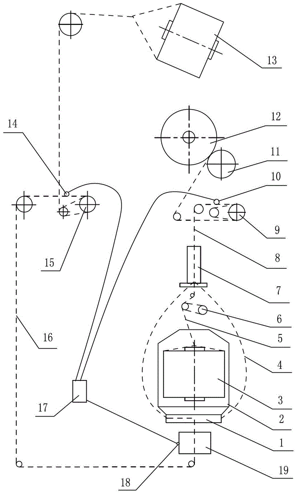
[0013] Implementation mode one: if figure 1 As shown, the twisting machine of the present invention includes a spindle 2 installed on a frame, a spindle drive motor 19, a twist leveler 7, an overfeeding device 9, an outer yarn tensioner 15, an inner yarn tensioner 6, a winding Device and control system 17, the spindle 2 includes a yarn pot and a twisting disc 1 located at the bottom of the yarn pot, and the winding device is mainly composed of a winding roller 11 and a yarn bobbin; one of the yarns is packaged from the outer yarn as the outer yarn 16 13 lead out, after being guided by multiple yarn passing wheels, the deflection is realized on the spindle twisting disk 1 in a direction approximately perpendicular to the axis of the spindle 2, and is introduced into the twist leveler 7 through the periphery of the spindle at the edge of the twisting disk 1, and the other strand The yarn is drawn from the inner yarn package 3 in the spindle 2 as the inner yarn 5, and is also int...

Embodiment approach 2

[0014] Embodiment 2: In the technical solution of Embodiment 1, only the outer yarn sensor 14 can be set to detect one or both of these two parameters, the outer yarn speed and the outer yarn tension, and the outer yarn speed and the outer yarn tension of the control system One or both of these two parameters are combined into a control parameter to control the outer yarn tensioner 15 to actively feed the wire at a constant speed or at a variable speed, and to control the change of the motor speed connected with the overfeeding wheel.

Embodiment approach 3

[0015] Embodiment 3: In the technical solution of Embodiment 1, only the ply yarn sensor 10 can be set to detect one or both of these two parameters of ply yarn speed and ply yarn tension, and the control system uses ply yarn speed and ply yarn One or both of these two parameters of the tension are combined into a control parameter to control the outer yarn tensioner 15 at a constant speed or variable speed to actively feed the wire, and to control the change of the motor speed connected with the overfeeding wheel.


PUM


Abstract

The invention discloses a straight twisting machine, and belongs to the field of textile machinery. The problems that external yarn tension control is not accurate, and an optimum ballooning shape cannot be reached exist in the existing straight twisting machine. The straight twisting machine is characterized in that an external yarn sensor is arranged in an external yarn path between a twisting tray and an external yarn tensioner and used for detecting an external yarn linear speed and external yarn tension; a strand yarn sensor is arranged in a strand yarn path between an overfeeding device and an even twisting device and used for detecting a strand yarn linear speed and strand yarn tension; a motor sensor is arranged on a spindle drive motor and used for detecting a motor speed and current; the external yarn tensioner and an overfeeding wheel of the overfeeding device are respectively driven by separate motors; a control system connected with the motors is connected with the external yarn sensor, the strand yarn sensor and the motor sensor; and by taking the external yarn speed, the external yarn tension, the spindle drive motor speed, the current, the strand yarn linear speed and the strand yarn tension as parameters, the control system controls the external yarn tensioner to actively feed yarns at a constant speed or a variable speed, adjusts a strand yarn pulling speed, and ensures that a tension value of an external yarn can allow a wrapping angle to be minimum.

Description

technical field [0001] The invention belongs to the technical field of textile machinery, and in particular relates to a direct twisting machine with low energy consumption and low noise. Background technique [0002] Direct twisting machine is a kind of textile machine mainly used to directly combine two yarns into ply yarns, twist them into cords, and wind them into parallel bobbins. When combining and twisting, two strands of yarn are respectively introduced from two yarn packages, one of which is installed in the rotating spindle, and the other strand of yarn passes through the twisting disk of the spindle and passes outside the spindle , and then the two strands of yarn are merged into the twist leveler to form an inner yarn and an outer yarn, and the outer yarn will form a balloon during the rotation of the spindle. Before the yarn is introduced from the twisting disk to the balloon, the outer yarn is at least partially wrapped on the twisting disk, because the size...

Claims


Application Information

Patent Timeline
Patent Type & Authority Applications(China)
IPC IPC(8): D01H1/00D01H13/32
Inventor 蔡国辉张超马少华
Owner ZHEJIANG RIFA TEXTILE MASCH CO LTD
Why Eureka
Try Eureka