
Construction method of prestressed anchor cable

A technology of prestressed anchor cables and construction methods, which is applied in the direction of foundation structure engineering, buildings, sheet pile walls, etc., and can solve the problem of the difficulty in completely ensuring the grouting quality and prestressing effect of the inner anchorage section, the difficulty in ensuring the grouting pressure of the inner anchorage section, and the difficulty of anchoring In order to improve the overall economic benefits, lower the cost and improve the yield

Active Publication Date: 2013-06-12
YELLOW RIVER ENG CONSULTING
View PDF5 Cites 22 Cited by
  • Summary
  • Abstract
  • Description
  • Claims
  • Application Information

AI Technical Summary

Problems solved by technology

Because there is often a gap between the grout stop ring and the hole wall of the anchor cable hole, the grout stop effect is poor, not only the length of the tension section is difficult to ensure, but also the grouting pressure of the inner anchor section is not easy to guarantee, resulting in the effect of prestressing the anchor cable poor
In the case of poor geological conditions, even if some proprietary technology is adopted, it is still difficult to fully guarantee the grouting quality and prestressing effect of the inner anchorage section because the length of the grout stop section is only about 400mm

Method used


Image

  • Construction method of prestressed anchor cable
  • Construction method of prestressed anchor cable
  • Construction method of prestressed anchor cable

Examples


Embodiment Construction

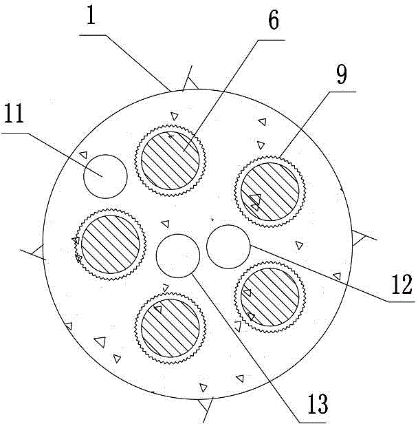
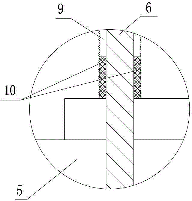
[0014] like figure 1 , 2 , Shown in 3, prestressed anchor cable construction method of the present invention, carry out according to the following steps:

[0015] The first step, according to the design requirements, adopt the drilling method to drill the anchor cable hole 1;

[0016] The second step is to make the anchor cable according to the designed length: the anchor cable is composed of an inner anchor section 3, a tension section 4, and a grout stop ring 5 installed between the interface between the inner anchor section 3 and the tension section 4; the inner anchor section 3 passes through The beam rings 7 and spacers 8 installed alternately on multiple steel strands 6 at intervals are made into a corrugated shape, and the tension section 4 is made into a linear shape through the spacers 8 installed on multiple steel strands 6 at intervals. Each steel strand 6 located in the tension section 4 is fitted with a casing 9, and the lower end of each casing 9 is sealed at t...


PUM


Abstract

The invention discloses a construction method of a prestressed anchor cable, which comprises the steps of drilling anchor cable holes, fabricating the anchor cable, mounting the anchor cable, erecting an anchor pier, injecting slurry in the anchor cable holes and tensioning the anchor cable according to a design requirement, wherein in the step of fabricating the anchor cable, an inner anchoring section is fabricated into a ripple shape by wire bunching rings and isolating frames that are alternately mounted on steel strands at intervals; a tensioning section is fabricated into a straight-line shape by the isolating frames mounted on the steel strands at intervals; sleeves are mounted on the steel strands of the tensioning section in a sleeving manner; the lower end parts of the sleeves, which are located at a slurry stopping ring, are sealed by structural adhesives; in the step of injecting the slurry in the anchor cable holes, the slurry is injected in the tensioning section anchor cable hole by a tensioning section slurry injection pipe; after the sand slurry is solidified, the slurry is injected in the inner anchoring section anchor cable hole by an inner anchoring section slurry injection pipe; and after the slurry injection of the inner anchoring section is accomplished, the step of tensioning the anchor cable is conducted. The construction method has the advantages that the tensioning section accomplishing the slurry injection serves as the slurry stopping ring for the slurry injection of the inner anchoring section, and a slurry stopping effect can be ensured under any rock mass conditions, so that the quality of the whole anchor cable is ensured.

Description

technical field [0001] The invention relates to a prestressed anchor cable used for rock mass reinforcement, in particular to a prestressed anchor cable construction method. Background technique [0002] The prestressed anchor cable used for rock mass reinforcement generally adopts the secondary grouting type, and the inner anchorage section and the tension section are separated by a grout stop ring. During anchor cable construction, the first grouting is carried out to the inner anchor section to form a complete inner anchor section, then the anchor cable is tensioned, and finally the tension section is grouted for the second time. Because there is often a gap between the grout stop ring and the hole wall of the anchor cable hole, the grout stop effect is poor, not only the length of the tension section is difficult to ensure, but also the grouting pressure of the inner anchor section is not easy to guarantee, resulting in the effect of prestressing the anchor cable poor. ...

Claims


Application Information

Patent Timeline
IPC IPC(8): E02D5/74
Inventor 董昊雯
Owner YELLOW RIVER ENG CONSULTING
Learn More