Vehicle transmission system testing method and test table for implementing same
A technology of a transmission system and a test method, which is applied in the field of vehicle transmission system testing and the test bench for implementing the same, can solve problems such as the inability to accurately reflect the power and economy of the vehicle, and achieve the purpose of reducing fatigue, improving accuracy and accurate test data. Effect
Inactive Publication Date: 2013-06-12
HENAN UNIV OF SCI & TECH
View PDF9 Cites 10 Cited by
- Summary
- Abstract
- Description
- Claims
- Application Information
AI Technical Summary
Problems solved by technology
[0007] The purpose of the present invention is to provide a vehicle transmission system test method and a test bench using the method, in order to solve the problem that the traditional vehicle trans
Method used
View moreImage
Smart ImageViewing Examples
Examples
 PUM
 Abstract
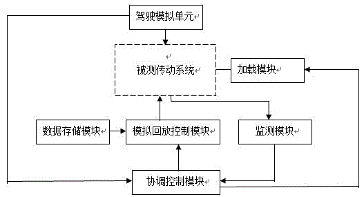
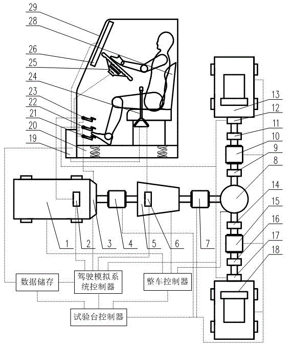
The invention relates to a vehicle transmission system testing method and a test table for implementing the same. The vehicle transmission system testing method comprises the following steps that at first, a driver operates a driving simulation unit to simulate working states of a transmission system under various working conditions according to road condition information stored in the driving simulation unit, and data in a process that the operator operates a test is stored into a data storage module; and after the driver simulates the various working conditions, the transmission system starts to enter a non-driver operation mode, a transmission system to be tested can be controlled by a control system according to the data stored in the data storage module, and various working conditions can be repeatedly simulated under the non-driver operation mode, so that the relative test can be completed. The problem that the intrinsic working condition circulating system of the testing table of the traditional transmission system cannot accurately respond relative property indexes, such as a dynamic property, an economical efficiency and the like in a vehicle actual operation process, can be solved.
Description
technical field [0001] The invention relates to a test method for a vehicle transmission system and a test stand for implementing the method. Background technique [0002] Vehicle transmission system test bench has far-reaching and important significance to the design and development of vehicle transmission system. The test bench system can provide the same test and debugging environment as the whole vehicle for each component assembly; it can perform performance evaluation on each component and assembly; it can complete vehicle power, economy and other related tests. Through the bench test, the vehicle controller can be tested and the key problems that cannot be solved by power integration and simulation technology can be solved. [0003] The traditional vehicle transmission system test bench is based on the computer setting working conditions to control the whole test bench system. The obtained results of fuel economy and dynamic performance have an important relationship...
Claims
Login to View More Application Information
Patent Timeline
 IPC IPC(8): G01M13/02
CPCG01M13/025
Inventor 郗建国高振萍高建平高玮牛毅张孝友侯海源张晓博乔宏冰韩梅梅葛坚
Owner HENAN UNIV OF SCI & TECH
Features
- R&D
- Intellectual Property
- Life Sciences
- Materials
- Tech Scout
- Unparalleled Data Quality
- Higher Quality Content
- 60% Fewer Hallucinations
Learn More Browse by: Latest US Patents, China's latest patents, Technical Efficacy Thesaurus, Application Domain, Technology Topic, Popular Technical Reports.
© 2025 PatSnap. All rights reserved.Legal|Privacy policy|Modern Slavery Act Transparency Statement|Sitemap|About US| Contact US: help@patsnap.com


