Optical element adjusting seat

A technology of optical components and adjustment seats, applied in the direction of optical components, optics, installation, etc., can solve problems such as vibration interference, spring deformation, and inability to bear large weights, and achieve the effect of firm fixation and high stability

Active Publication Date: 2013-06-12
INST OF SEMICONDUCTORS - CHINESE ACAD OF SCI
View PDF4 Cites 2 Cited by
  • Summary
  • Abstract
  • Description
  • Claims
  • Application Information

AI Technical Summary

Problems solved by technology

[0003] However, for figure 1 As shown in the optical element adjustment frame, the fixed frame and the adjustable frame are separated from each other, which are easily disturbed by spring deformation and external vibration, and the optical stability is not high.
However, the UV adhesive bonding lens method with high stability is not adjustable or can only b

Method used


Image

  • Optical element adjusting seat
  • Optical element adjusting seat
  • Optical element adjusting seat

Examples


Embodiment Construction

[0029] In order to make the object, technical solution and advantages of the present invention clearer, the present invention will be described in further detail below in conjunction with specific embodiments and with reference to the accompanying drawings. It should be noted that, in the drawings or descriptions of the specification, similar or identical parts all use the same figure numbers. Implementations not shown or described in the accompanying drawings are forms known to those of ordinary skill in the art. Additionally, while illustrations of parameters including particular values ​​may be provided herein, it should be understood that the parameters need not be exactly equal to the corresponding values, but rather may approximate the corresponding values ​​within acceptable error margins or design constraints. In addition, the directional terms mentioned in the following embodiments, such as "upper", "lower", "front", "rear", "left", "right", etc., are only referring t...


PUM


Abstract

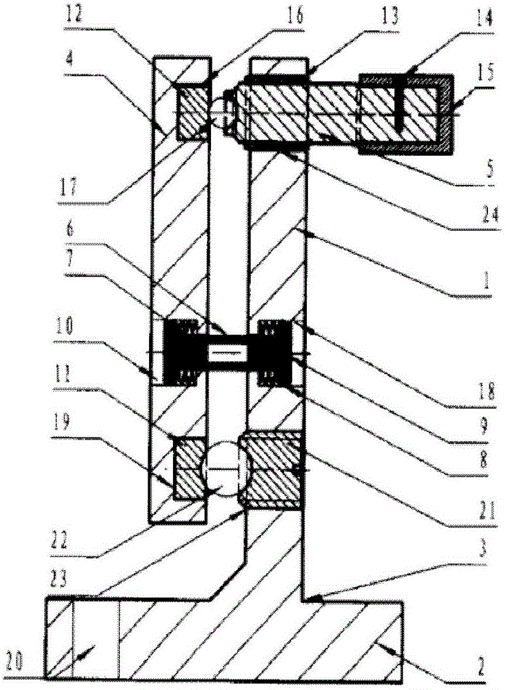
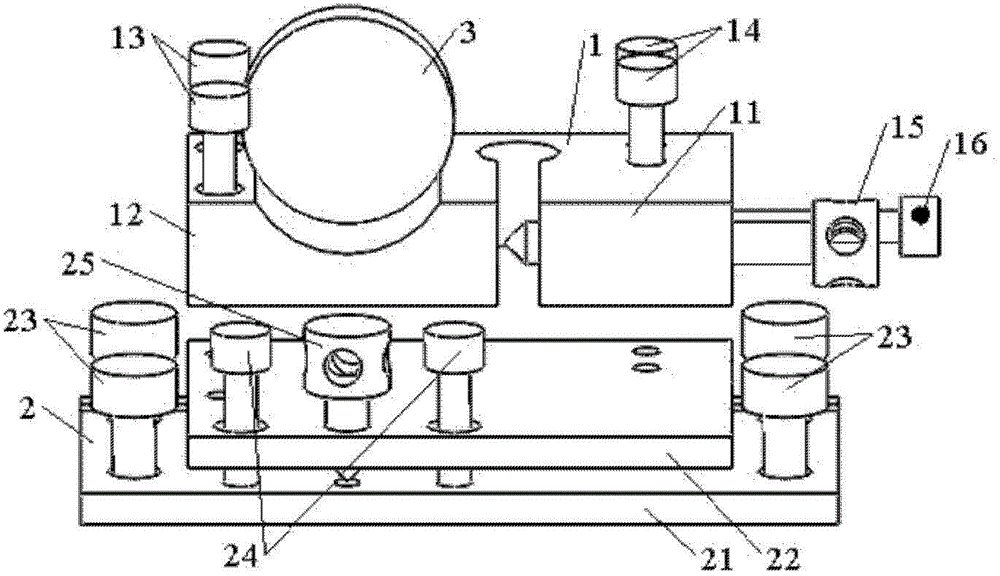
The invention provides an optical element adjusting seat. In the optical element adjusting seat, an optical element is adhered and fixed to a first elastic plate, and a first threaded ejector rod is used for regulating the angle in a horizontal direction; and a second elastic plate is used to regulate the angle of the optical element in a vertical direction by using the same principle, and thus, the two-dimensional regulation of the optical element is realized.

Description

technical field [0001] The invention relates to the field of laser technology in the optical industry, in particular to an optical element adjustment seat. Background technique [0002] Usually, in laser devices, the adjustment methods of optical lenses or other components are mostly the way of using a fixing frame to cooperate with an adjusting frame or bonding with ultraviolet light glue. figure 1 It is a schematic diagram of the prior art optical element adjustment frame. Such as figure 1 As shown, the adjustment frame is based on a threaded ejector rod combined with a spring or screw tension structure, and the lens is fixed on the vertical fixing frame by pressing or pushing. [0003] However, for figure 1 As shown in the optical element adjustment frame, the fixed frame and the adjustment frame are separated from each other, which are easily disturbed by spring deformation and external vibration, and the optical stability is not high. The high-stability UV-adhesive ...

Claims


Application Information

Patent Timeline
IPC IPC(8): G02B7/00
Inventor 林学春鄢歆张志研李梦龙晏诗恋于海娟侯玮徐贵昌
Owner INST OF SEMICONDUCTORS - CHINESE ACAD OF SCI
Why Eureka
Try Eureka