Light-emitting key structure

A technology of buttons and light-emitting elements, applied in electrical components, electrical switches, circuits, etc., can solve problems such as inconvenience for users to operate

Active Publication Date: 2013-06-12
DARFON ELECTRONICS (SUZHOU) CO LTD +1
View PDF4 Cites 9 Cited by
  • Summary
  • Abstract
  • Description
  • Claims
  • Application Information

AI Technical Summary

Problems solved by technology

[0003] In view of the problems in the prior art, one of the objects of the present invention is to provide a light-emitting key structure, which uses a shading member to shield the reflected light traveling to the lower edge of the ke...

Method used


Image

  • Light-emitting key structure
  • Light-emitting key structure
  • Light-emitting key structure

Examples


Embodiment Construction

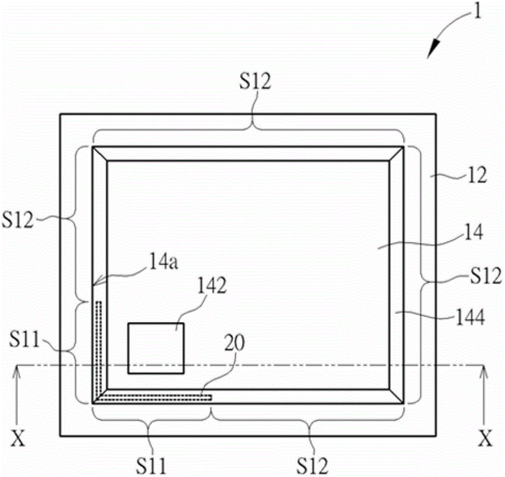
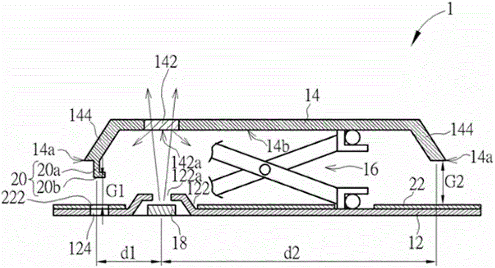
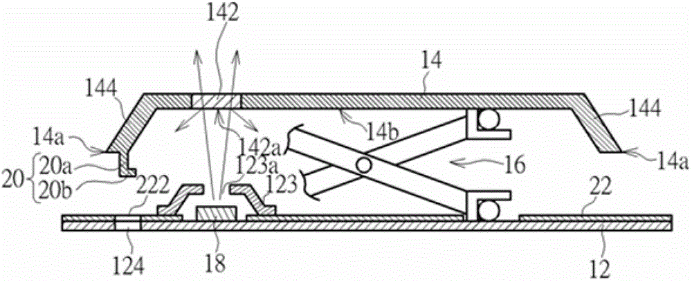
[0031] see figure 1 and figure 2 , figure 1 It is a top view of a preferred embodiment of the luminous key structure 1 of the present invention, figure 2 Illuminated button structure 1 edge figure 1 The schematic cross-sectional view of the middle line X-X, where other components usually configured in the actual operation of the light-emitting key structure 1, such as elastic round protrusions, etc., are omitted for the sake of simplification of the drawing and description. The key structure 1 includes a bottom plate 12 , a keycap 14 , a lifting mechanism 16 , a light emitting element 18 , a light-shielding element 20 and a film circuit board 22 . The keycap 14 is arranged on the bottom plate 12, and the lifting mechanism 16 connects the bottom plate 12 and the keycap 14, so that the keycap 14 can move up and down relative to the bottom plate 12 by using the lifting mechanism 16; in this embodiment, the lifting mechanism 16 is a scissors type Lifting mechanism, but the p...


PUM


Abstract

The invention relates to a light-emitting key structure, comprising a bottom plate, a key cap, a light-emitting element and a light-shading element, wherein the key cap is arranged on the bottom plate and can move up and down relatively to the bottom plate; and the key cap is provided with a periphery and a light-transmitting part positioned at the inner side of the periphery. The light-emitting element is arranged under the light-transmitting part and can emit light. The light-shading element is arranged between the key cap and the bottom plate. The light part can emit out of the key cap through the light-transmitting part, and the shading part of the light-shading element does not enter the light of the light-transmitting part. Therefore, the light-shading element is arranged by mainly utilizing the limited space between the light-transmitting part and the periphery of the key cap so as to avoid the possibility that the overflowing of the light reflected by the bottom surface out of the key cap can be effectively and greatly restrained or eliminated due to interference with other structures.

Description

technical field [0001] The invention relates to a key structure, in particular to a luminous key structure. Background technique [0002] The traditional keyboard has no light-emitting function. When the ambient light is insufficient, unless the user is familiar with touch typing, the user may press the key by mistake, resulting in wrong input, which often causes troubles for the user in inputting. Therefore, currently there are keyboards with a light-emitting function, so that the user can still accurately know the position of the keys and perform input in an environment with insufficient light. However, the light is irradiated upwards from the bottom of the key. If it is not specially designed, in addition to the light produced by the permeable part of the keycap, the light may overflow from the lower edge of the keycap when it is reflected by the interface of the permeable part or the surface of other structural parts, which may interfere with the keycap. The user's reco...

Claims


Application Information

Patent Timeline
IPC IPC(8): H01H13/83H01H13/86
Inventor 蔡柏伟
Owner DARFON ELECTRONICS (SUZHOU) CO LTD
Why Eureka
Try Eureka