Supercharge Your Innovation With Domain-Expert AI Agents!

Bowl structure for a centrifugal concentrator

A bowl and liquid technology, applied in centrifuges, centrifuges with rotating drums, etc., can solve problems such as not achieving commercial success

Active Publication Date: 2013-06-12
F L SMIDTH & CO AS
View PDF21 Cites 6 Cited by
  • Summary
  • Abstract
  • Description
  • Claims
  • Application Information

AI Technical Summary

Problems solved by technology

This device was not commercially successful and the disclosure as a working device has long since been abandoned

Method used


Image

  • Bowl structure for a centrifugal concentrator
  • Bowl structure for a centrifugal concentrator
  • Bowl structure for a centrifugal concentrator

Examples


Embodiment Construction

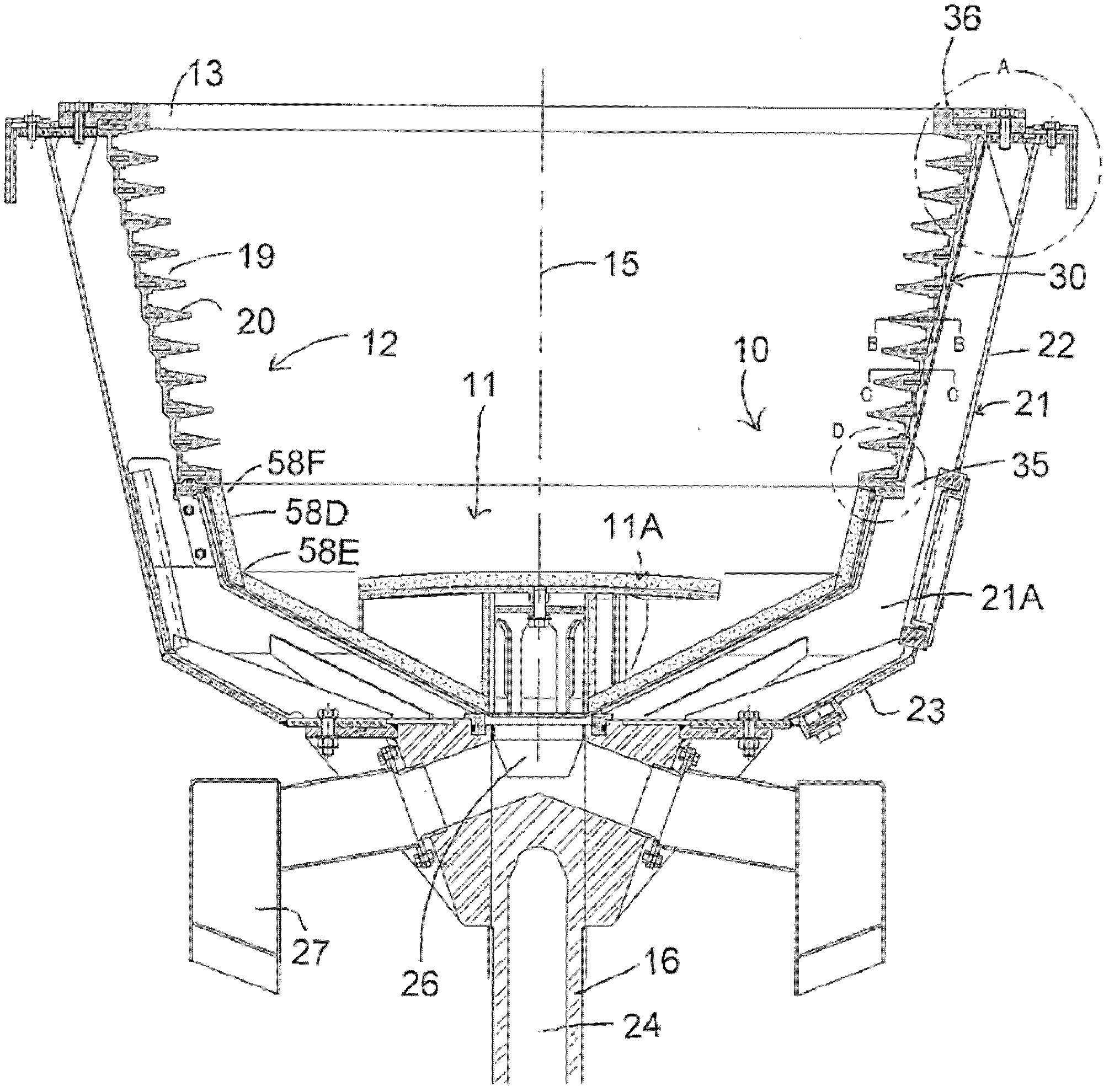
[0061] For example in the aforementioned US Patent 5,222,933 figure 1 The general arrangement of a centrifugal separator is shown in , and will therefore only be briefly described with reference to important points. Reference is made to the disclosure of the above-mentioned patents of the present assignee for further details which may be necessary for a full understanding.

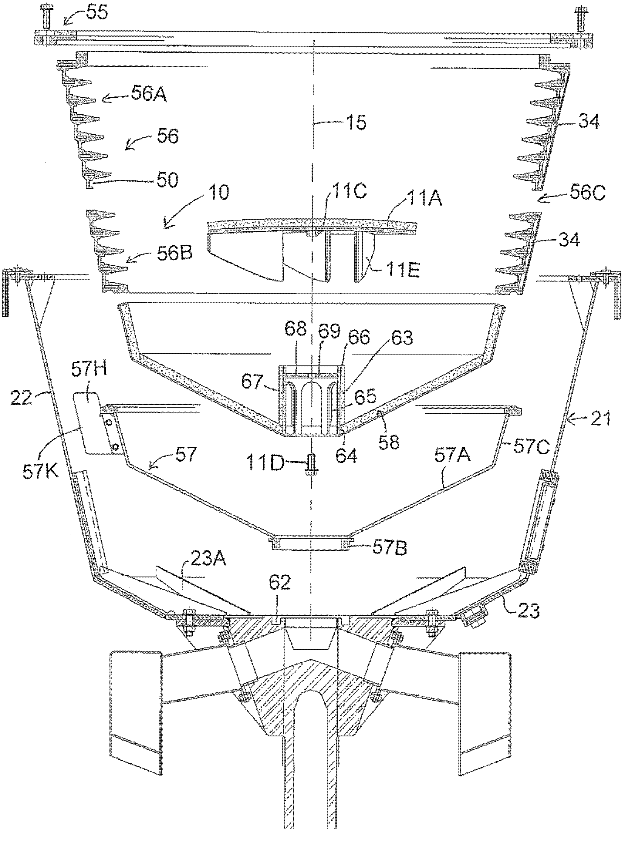
[0062] The device thus comprises a bowl generally indicated at 10 having a base generally indicated at 11 and a peripheral wall 12 standing upwards from said base to an open mouth 13 . The bowl is rotatable about an axis 15 on a support shaft 16 .

[0063] The feed pipe carries the feed material in the form of a mixture of heavier and lighter particulate materials in a slurry to a position adjacent the bottom 11 through the open mouth 13 so that the feed material can be deposited to a horizontal deflector pad at the bottom 11 (deflector pad) 11A and can move from it to the peripheral wall 12 to separate ...


PUM


Abstract

A centrifuge concentrator bowl has feed deposited onto a base of the bowl and includes a plurality of recesses at axially spaced positions along a peripheral wall of the bowl. The peripheral wall is formed of a rigid metal skeleton frame of rings and upstanding support members on which is molded a urethane liner material to form an integral structure with the rings located at ribs between the recesses. A fluidization water injection system includes an outer container on the bowl, which also acts as a clamping assembly, and a plurality of liquid entry openings through the peripheral wall at the base of the recesses allowing flexing of the peripheral wall in response to changes in pressure in the fluidizing liquid. The bowl is formed of separate sections defined by a bottom concave base section and the cast skeleton wall all clamped together to allow replacement of the separate parts.

Description

technical field [0001] The present invention relates to centrifugal separators of the type having a plurality of axially spaced annular grooves in the peripheral wall of a rotating bowl. Background technique [0002] 5,230,797; The centrifugal separator device of , wherein a plurality of axially spaced annular grooves are provided on said peripheral wall. Granular material comprising fractions of various specific weights to be separated is fed in the form of a slurry through a feed pipe to a location at or near the bottom of the bowl such that the feed material passes over the peripheral wall, wherein The heavier particulate material is collected in the annular groove and the lighter particulate material exits the bowl through the open mouth. In the above patent, all the annular grooves are fluidized by injecting fluidizing water through holes in the peripheral wall at each groove, thus serving to fluidize the material collected in the grooves. [0003] A further arrangem...

Claims


Application Information

Patent Timeline
Patent Type & Authority Applications(China)
IPC IPC(8): B04B7/08B04B15/00B04B15/12
CPCB04B1/00B04B7/08B04B15/12
Inventor E.J.W.宗尼维尔德D.科桑M.麦克利维M.J.富拉姆
Owner F L SMIDTH & CO AS
Features
  • R&D
  • Intellectual Property
  • Life Sciences
  • Materials
  • Tech Scout
  • Unparalleled Data Quality
  • Higher Quality Content
  • 60% Fewer Hallucinations
Learn More