
Wireless power transmission system

A power transmission and wireless technology, applied in electromagnetic wave systems, transportation and packaging, electric vehicles, etc., can solve problems such as unguaranteed transmission

Active Publication Date: 2013-06-12
OSSIA
View PDF4 Cites 49 Cited by
  • Summary
  • Abstract
  • Description
  • Claims
  • Application Information

AI Technical Summary

Problems solved by technology

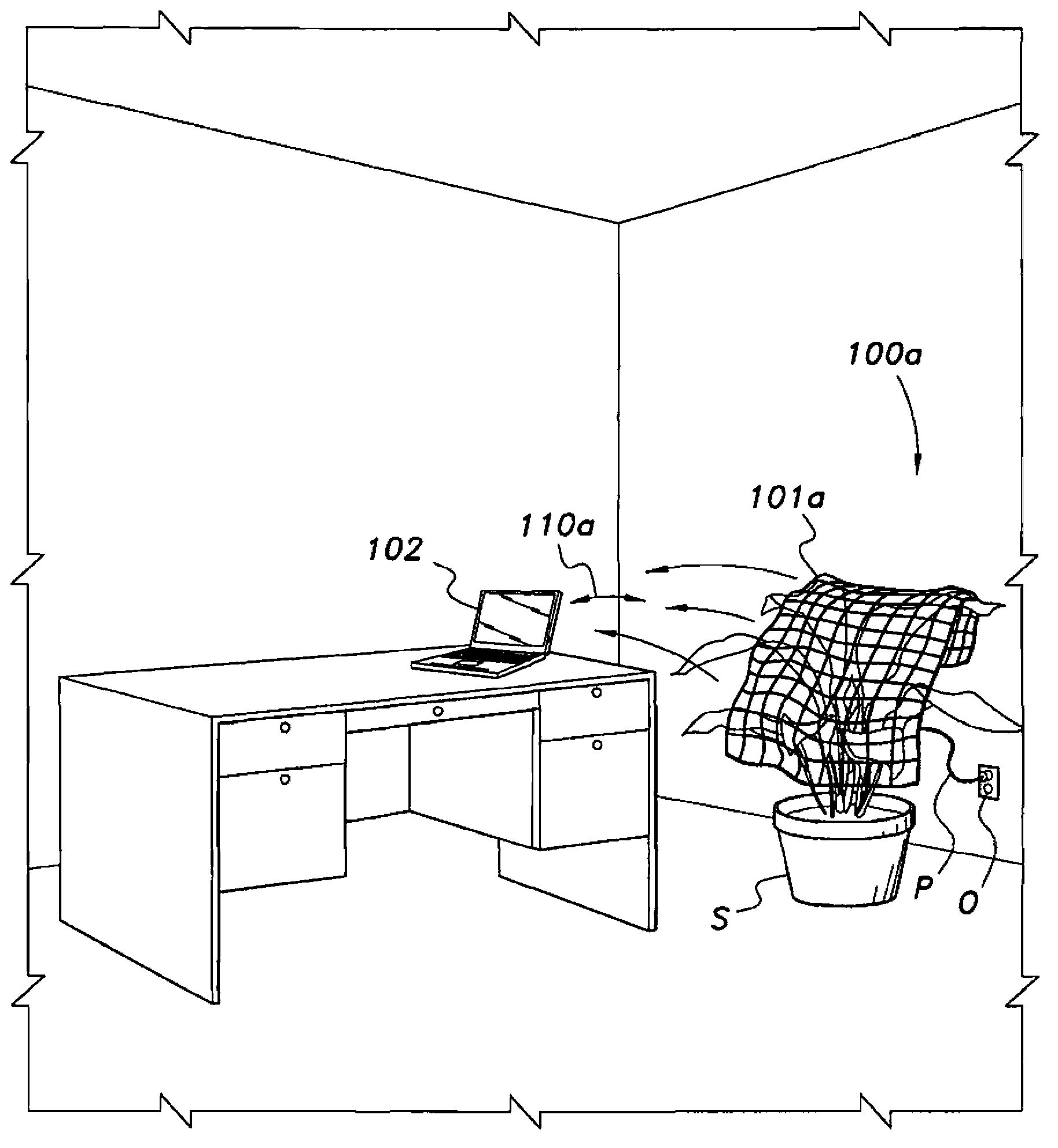
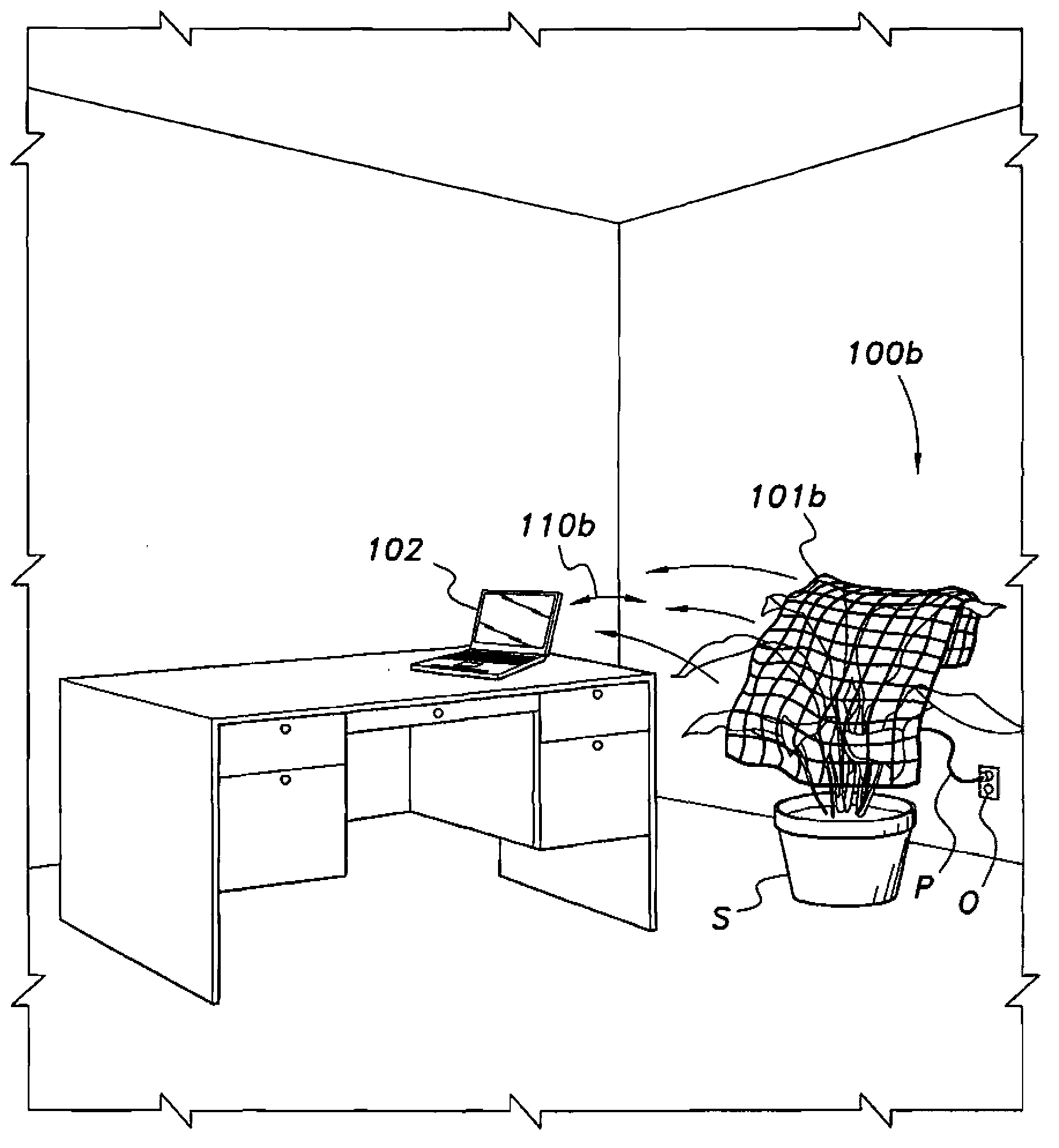
However, even if the device is located, effective transmission cannot be guaranteed due to reflections and interference from objects in or near the path of the receiving device

Method used


Image

  • Wireless power transmission system
  • Wireless power transmission system
  • Wireless power transmission system

Examples


Embodiment approach

[0100] 1. A wireless microwave power transmitter.

[0101] 2. According to the wireless microwave power transmitter described in embodiment 1, the wireless microwave power transmitter also includes a controller and a phased array antenna with multiple microwave array transceivers, and the multiple microwave array transceivers are used to send and receive letters Emit microwave power transmission signal.

[0102] 3. A wireless microwave power transmitter according to any preceding embodiment, wherein the transceivers are adaptively phased by a controller to transmit their respective power transfer signals at selected phases.

[0103] 4. A wireless microwave power transmitter according to any preceding embodiment, wherein each transceiver is further operable to receive a calibration signal from a device to be charged, and to detect the phase at which the calibration signal is received.

[0104] 5. A wireless microwave power transmitter according to any preceding embodiment, whe...


PUM


Abstract

The wireless power transmission is a system for providing wireless charging and / or primary power to electronic / electrical devices via microwave energy. The microwave energy is focused to a location in response to receiving a beacon signal from a beacon device by a power transmitter having one or more adaptively-phased microwave array emitters. Rectennas within the device to be charged receive and rectify the microwave energy and use it for battery charging and / or for primary power.

Description

[0001] Cross References to Related Applications [0002] This application claims the benefit of U.S. Provisional Application No. 12 / 861,526, filed August 23, 2010, which is a continuation-in-part of U.S. Patent Application Serial No. 11 / 812,060, filed June 14, 2007, Their contents are hereby deemed fully incorporated into this application by reference. technical field [0003] The present invention relates generally to power transfer systems and battery chargers, and more particularly to methods and systems for wireless power transfer to power devices requiring power via microwave transmission. Background technique [0004] Many portable electronic devices are powered by batteries. Rechargeable batteries are often used to avoid the cost of replacing conventional dry batteries and to conserve valuable resources. However, recharging batteries with conventional rechargeable battery chargers requires access to an alternating current (A.C.) power outlet, which is sometimes unav...

Claims


Application Information

Patent Timeline
IPC IPC(8): H02J17/00H02J7/00
CPCH02J50/20H02J50/23H02J50/27H02J50/40H02J50/70H02J50/80H02J50/90H02J7/025H02J7/007H02J50/402H04B5/79H02J7/0029
Inventor H·I·泽内
Owner OSSIA
Learn More