Injection moulding machine

A technology for injection molding machines and connecting rods, applied in the field of injection molding machines, can solve problems such as difficult working space and cumbersome operations, and achieve the effect of easy balance adjustment

Inactive Publication Date: 2013-06-19
SUMITOMO HEAVY IND LTD
View PDF6 Cites 7 Cited by
  • Summary
  • Abstract
  • Description
  • Claims
  • Application Information

AI Technical Summary

Problems solved by technology

[0007] Conventionally, when performing balance adjustment on multiple connecting rods, it was cumbersome to attach and remove strain gauges from each connecting rod.
Since various parts are placed around the connecting rod, it becomes difficult to secure a sufficient working space

Method used


Image

  • Injection moulding machine
  • Injection moulding machine
  • Injection moulding machine

Examples


no. 1 Embodiment approach

[0040] The injection molding machine of the present embodiment is provided with a mold clamping device using a motor and a toggle mechanism.

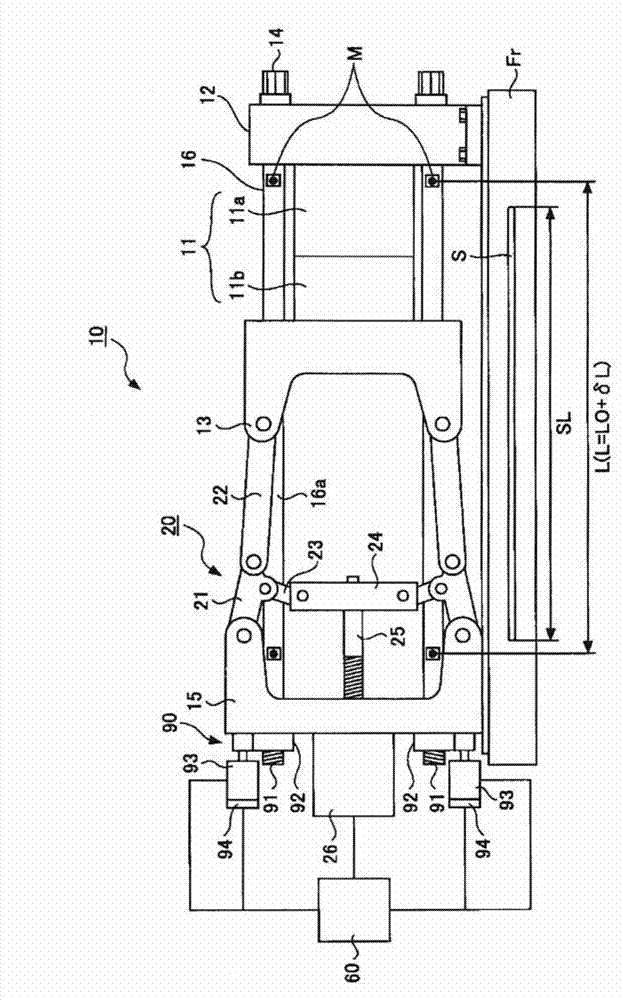
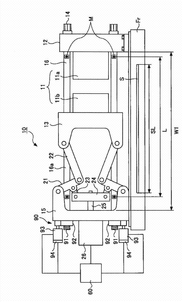
[0041] figure 1 It is a figure which shows the state at the time of mold closing of the injection molding machine of 1st Embodiment. figure 2 It is a figure which shows the state at the time of mold opening of the injection molding machine of 1st Embodiment.

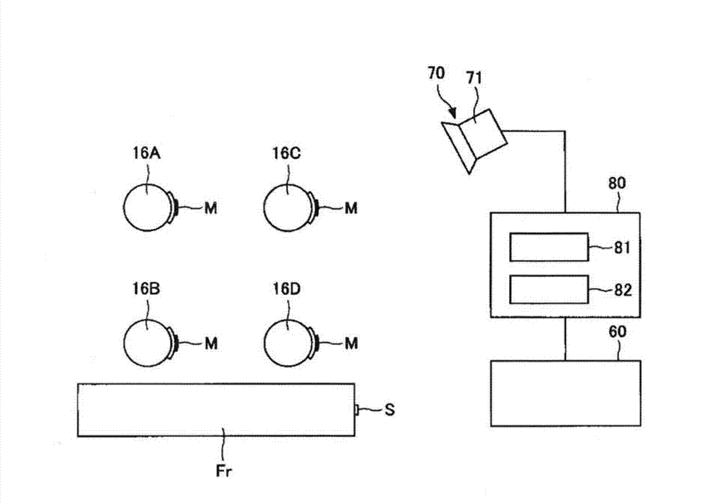
[0042] The injection molding machine 10 includes: a fixed platen 12 to which a fixed mold 11a is mounted; a movable platen 13 to which a movable mold 11b is mounted; a toggle support 15 as a base member provided at a distance from the fixed platen 12; Multiple (for example, four) connecting rods 16 for fixing the pressing plate 12 and the toggle support 15 . The mold apparatus 11 is comprised by the fixed mold 11a and the movable mold 11b.

[0043] The fixed platen 12 is fixed to the frame Fr. A movable platen 13 is arranged opposite to the fixed platen 12 . A guide hole (no...

no. 2 Embodiment approach

[0110] The injection molding machine according to the first embodiment described above includes a mold clamping device using a motor and a toggle mechanism. On the other hand, the injection molding machine of this embodiment is different in that it is provided with a mold clamping device that uses a linear motor for the mold opening and closing operation and utilizes the attraction force of an electromagnet for the mold closing operation.

[0111] Figure 7 It is a figure which shows the state at the time of mold closing of the injection molding machine of 2nd Embodiment. Figure 8 It is a figure which shows the state at the time of mold opening of the injection molding machine of 2nd Embodiment.

[0112] The injection molding machine 110 includes: a fixed platen 112 to which a fixed mold 111a is mounted; a movable platen 113 to which a movable mold 111b is mounted; a rear platen 115 serving as a base member provided at a distance from the fixed platen 112; 112 and a plurali...


PUM


Abstract

The invention provides an injection moulding machine capable of carrying out balanced adjustment to a plurality of connecting rods. The injection moulding machine (10) is provided with a connecting rod (16) extending according to a mold clamping force applied on a fixed mold (11a) and a movable mold (11b). the injection moulding machine is characterized in that the connecting rod (16) is provided with a marker (M) used for image measurement of an elongation of the connecting rod (16).

Description

technical field [0001] The invention relates to injection molding machines. Background technique [0002] An injection molding machine fills a cavity space of a mold device with molten resin, and solidifies it to form a molded product (for example, refer to Patent Document 1). The mold device is composed of a fixed mold and a movable mold, and a cavity space is formed between the fixed mold and the movable mold when the mold is closed. The mold closing, mold clamping and mold opening of the mold device are performed by the mold clamping device. [0003] The mold clamping device includes: a fixed platen, with a fixed mold; a movable platen, with a movable mold; a base part, separated from the fixed platen; and multiple (for example, 4) connecting rods, connecting the fixed platen and the base part . The mold closing, mold clamping and mold opening of the mold device are carried out by moving the movable platen forward and backward along the connecting rod. [0004] Since ...

Claims


Application Information

Patent Timeline
IPC IPC(8): B29C45/76B29C45/64
Inventor 斋藤悠佑
Owner SUMITOMO HEAVY IND LTD
Why Eureka
Try Eureka