Image recording apparatus

a recording apparatus and image technology, applied in the field of image recording apparatus, can solve the problems of inaccurate positional relationship between the positioning bore and the recorded image, difficult to rotate the recording drum with high accuracy, and inability to accurately position the recording material on the recording drum, etc., to achieve accurate positional relationship and simple balance adjustment of the recording drum

Active Publication Date: 2006-07-11
DAINIPPON SCREEN MTG CO LTD
View PDF16 Cites 0 Cited by
  • Summary
  • Abstract
  • Description
  • Claims
  • Application Information

AI Technical Summary

Benefits of technology

[0009]The object of this invention, therefore, is to provide an image recording apparatus capable of accurately maintaining a positional relationship between an image recorded on a recording material and a positioning bore, and enabling a simple balance adjustment of a recording drum.
[0017]With this image recording apparatus, the accuracy of the positional relationship between a punch bore formed by the punch unit and a recorded image may be improved without positioning the recording material on the peripheral surface of the recording drum with high precision. Moreover, the punch unit need not be attached to the recording drum since the moving mechanism is provided for moving the punch unit between a standby position separated from the recording drum and a punching position. Thus, there is no need to adjust the weight balance of the recording drum when customizing the punch unit.

Problems solved by technology

This method has a drawback that, where the recording material is a soft material, a deformation of the recording material makes it impossible to position the recording material accurately on the recording drum.
This results in an inaccurate positional relationship between the positioning bore and a recorded image.
When the recording drum is rotated at high speed, the weight of the punch unit will make it difficult to rotate the recording drum with high accuracy unless the weight balance of the entire recording drum is adjusted accurately.
When the punch unit is customized, it is necessary to perform an adjustment of the weight balance of the recording drum again, and hence a drawback of the punch unit not being easy to customize.

Method used


Image

  • Image recording apparatus
  • Image recording apparatus
  • Image recording apparatus

Examples


Embodiment Construction

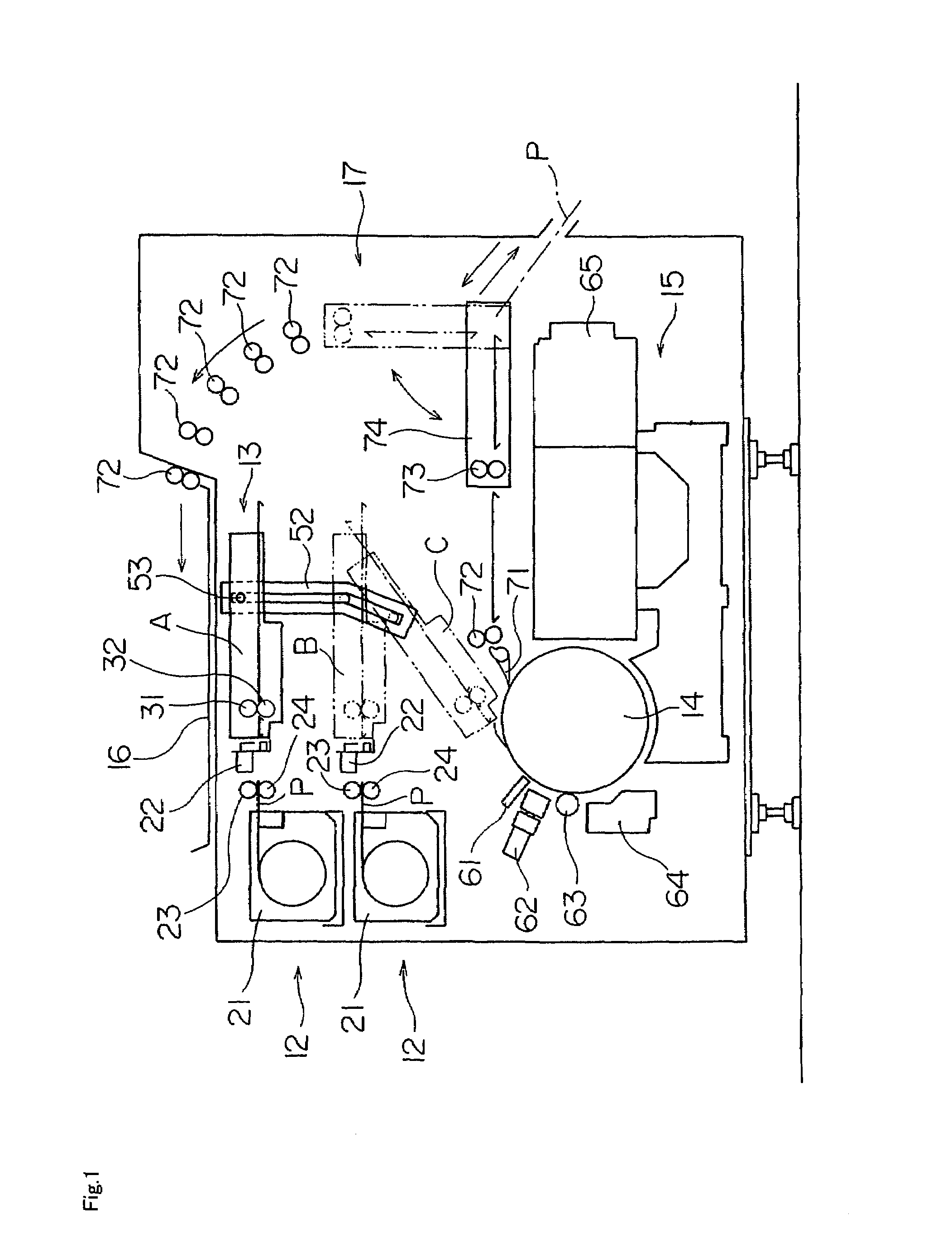
[0046]An embodiment of this invention will be described hereinafter with reference to the drawings. FIG. 1 is a schematic view of an image recording apparatus according to this invention.

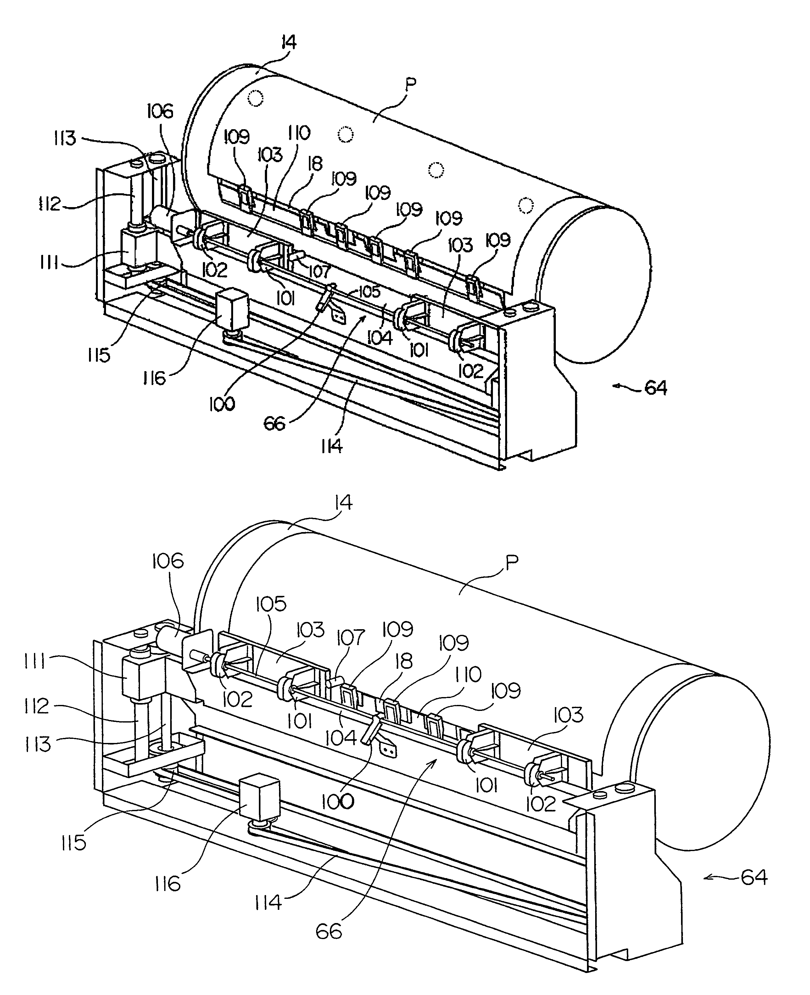
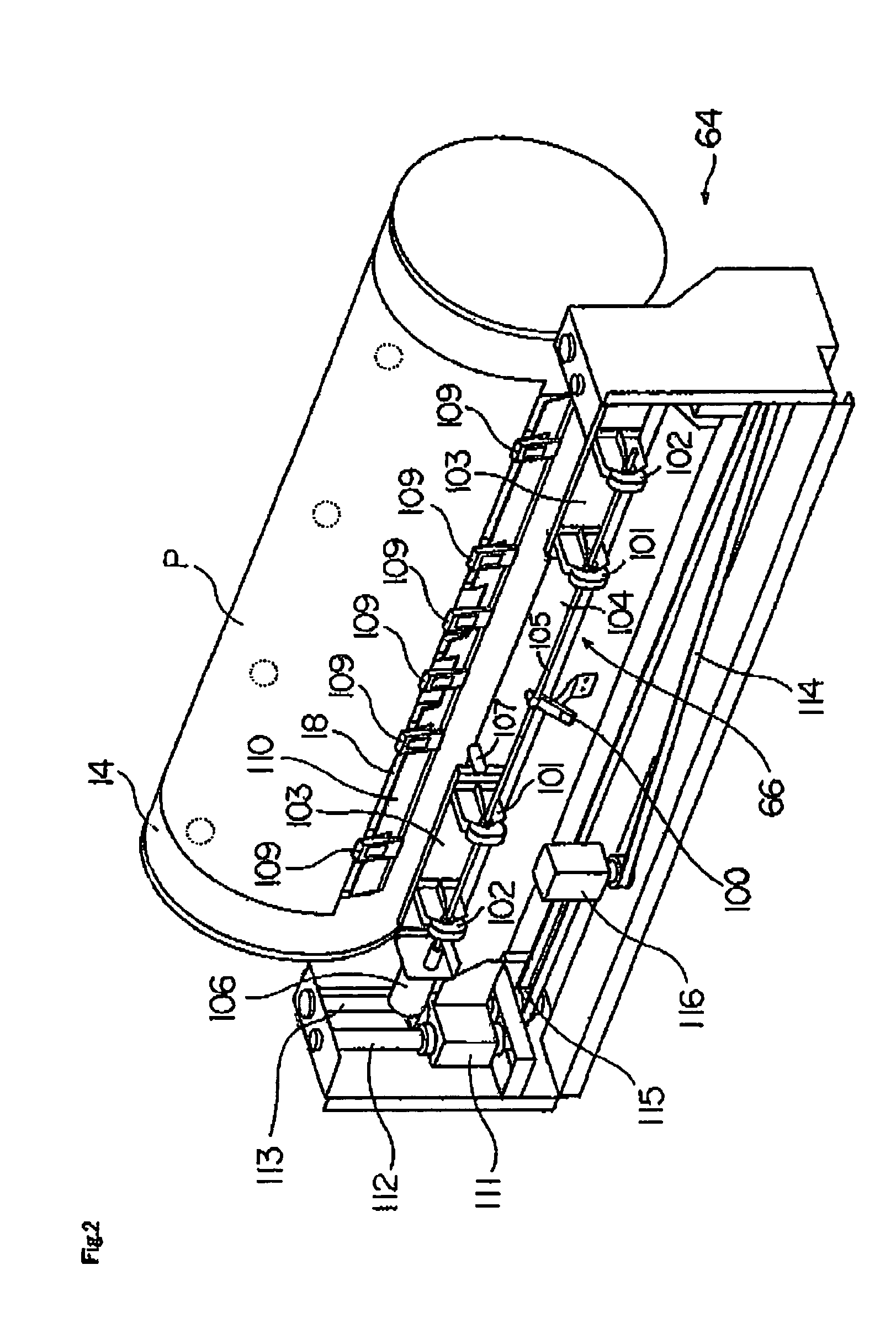
[0047]The image recording apparatus includes two recording material storage sections 12 arranged vertically, a recording material transport device 13 used for transporting a recording material P, a lift mechanism for raising and lowering the transport device 13, a tilt mechanism having a cam 52 and a cam follower 53 for tilting the transport device 13, a recording drum 14 for supporting the recording material P mounted peripherally thereof, an image recorder 15 for recording an image on the recording material P mounted on the recording drum 14, and a discharge mechanism 17 for discharging the recording material P having the image recorded thereon to a discharge tray 16.

[0048]Each of the recording material storage sections 12 includes a magazine 21 storing an elongate recording material P in roll for...


PUM

PropertyMeasurementUnit
suctionaaaaaaaaaa
colorsaaaaaaaaaa
speedaaaaaaaaaa

Abstract

A punch unit includes punch blocks supported by an arm through support plates. The arm has, arranged thereon, a motor for rotating a drive rod, a detector for detecting rotation angles of the drive rod, and a sensor for detecting a forward end of a recording material. The punch unit is movable by a moving mechanism including support members arranged at opposite ends of the arm, slide shafts and ball screws connected to the support members, and a pulse motor for driving the ball screws through a synchronous belt and synchronous pulleys.

Description

BACKGROUND OF THE INVENTION[0001]1. Field of the Invention[0002]This invention relates to an image recording apparatus for recording an image by emitting light beams to a recording material mounted on a recording drum.[0003]2. Description of the Related Art[0004]When printing in four color inks of yellow (Y), magenta (M), cyan (C) and black (K), for example, the same positional relationship must be maintained, for each of the YMCK colors, between a positioning bore for the printing machine used in positioning a printing plate, and an image recorded on the printing plate. The term “positioning bore for the printing machine” used in this specification includes a positioning bore used in placing the printing plate on a plate cylinder of the printing machine, and also a punch bore such as a positioning bore used in placing the printing plate on a puncher for forming a further punch bore in the printing plate.[0005]In a method proposed in U.S. Pat. No. 6,213,020 (hereinafter called “the ...

Claims


Application Information

Patent Timeline
Patent Type & Authority Patents(United States)
IPC IPC(8): B41F27/12B41C1/10G03F9/00
CPCB41C1/1083
Inventor TAMURA, TOSHIOKAWADA, TORUTANAKA, HIROHISAOKU, KATSUJI
Owner DAINIPPON SCREEN MTG CO LTD
Why Eureka
Try Eureka