
Energy meter power connection box

A power connection and electric energy meter technology, applied in the direction of measuring electric variables, measuring devices, instruments, etc., can solve problems affecting work efficiency, many processes, hidden dangers, etc., and achieve the effects of safe and reliable wiring, convenient use, and high work efficiency

Active Publication Date: 2015-09-23
MIDDLE SOUTH METER
View PDF6 Cites 0 Cited by
  • Summary
  • Abstract
  • Description
  • Claims
  • Application Information

AI Technical Summary

Problems solved by technology

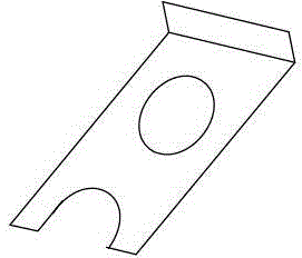
[0002] In the prior art, the structure of the electric energy meter power supply connection box is to directly connect the connecting piece (such as figure 1 As shown) is fixed on the fixed electrode, the connecting piece and the fixed electrode are tightly pressed and conductive structure, if the power connection is to be disconnected, usually by loosening the upper and lower fixing screws at the same time, and moving the connecting piece, in order to prevent the connecting piece from being affected by gravity To connect the circuit after falling down naturally, one hand needs to use an insulating tool to lift the connecting piece at the corner of the connecting piece, and the other hand tightens the upper fixing screw. After the wiring is completed, the upper fixing screw must be loosened to let the connecting piece fall naturally. Then tighten the upper and lower fixing screws, the following problems exist in the prior art: there are potential safety hazards, if the upper fixing screws are not tightened, the connecting piece will naturally fall down and there is a risk of electric shock; when wiring, there are many actions, which affects work efficiency; connecting piece processing When punching first, then bending, there are many processes

Method used


Image

  • Energy meter power connection box
  • Energy meter power connection box
  • Energy meter power connection box

Examples


Embodiment Construction

[0020] Now in conjunction with accompanying drawing, the present invention will be further described:

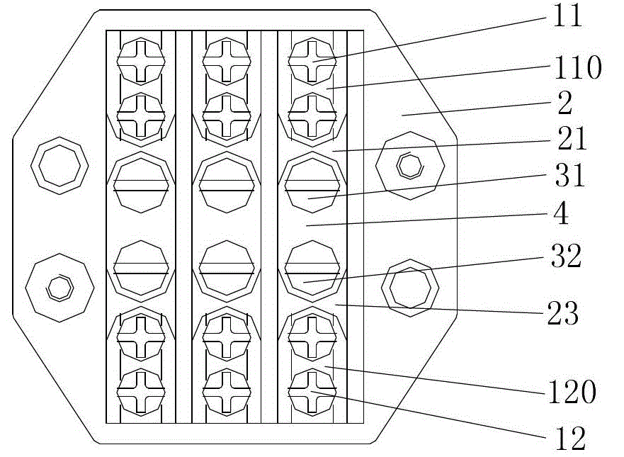
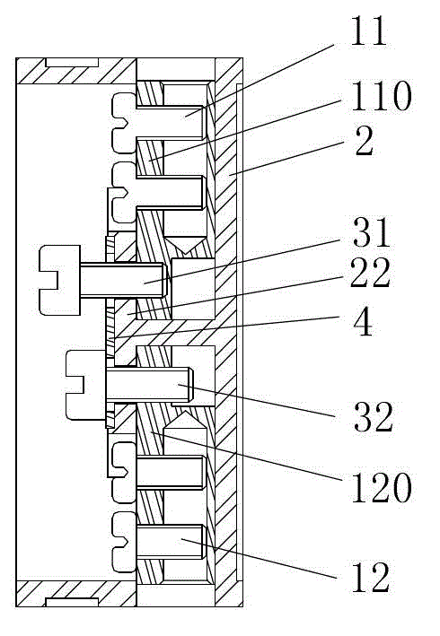
[0021] Such as Figure 2 to Figure 4 As shown, the insulating fixing frame 2 is provided with several groups of connecting terminals, and the connecting terminals include: an upper fixed electrode 110; a plurality of upper fixing screws 11 screwed into the upper fixed electrode 110; a lower fixed electrode 120; screwed into the lower fixed electrode A plurality of lower fixing screws 12 of 120; connecting piece 4, which is provided with an upper through hole and a lower through hole; upper screw 31, inserted into the upper through hole and screwed into the upper fixed electrode 110 to fix the connecting piece 4; lower screw 32, inserted into the lower The through hole is screwed into the lower fixed electrode 120 to fix the connecting piece 4;

[0022] An insulating layer 22 is provided between the connecting piece 4 and the upper fixed electrode 110 and the lower fixed ele...


PUM


Abstract

The invention discloses a power supply connection box of an electric energy meter. The power supply connection box of the electric energy meter comprises an insulating fixed frame, a plurality of groups of connecting terminals are arranged on the insulating fixed frame, wherein the connecting terminals comprise upper fixed electrodes; a plurality of fixed screws which are twisted on the upper fixed electrodes; lower fixed electrodes; a plurality of inlet wire fixed screws which are twisted on the lower fixed electrodes; connecting pieces, upper through holes and lower through holes are formed in the connecting pieces; upper screws, the upper screws are inserted into the upper through holes and twisted into the fixed connecting pieces of the upper fixed electrodes; and lower screws, the lower screws are inserted into the lower through holes and twisted into the fixed connecting pieces of the lower fixed electrodes; insulation layers are arranged between the connecting pieces and the upper fixed electrodes and between the connecting pieces and the lower fixed electrodes, and the insulation layers and the insulating fixed frame are combined into one; and limit blocks which limit the connecting pieces from moving left and right are arranged on the insulating fixed frame. The upper through holes and lower through holes of the connecting pieces are larger than the diameters of the thread portions of the upper screws and the lower screws. The power supply connection box of the electric energy meter has the advantages of being reliable and secure in wire connection, high in working efficiency, and convenient to use.

Description

technical field [0001] The invention relates to a power supply connection box for an electric energy meter. Background technique [0002] In the prior art, the structure of the electric energy meter power supply connection box is to directly connect the connecting piece (such as figure 1 As shown) is fixed on the fixed electrode, the connecting piece and the fixed electrode are tightly pressed and conductive structure, if the power connection is to be disconnected, usually by loosening the upper and lower fixing screws at the same time, and moving the connecting piece, in order to prevent the connecting piece from being affected by gravity To connect the circuit after falling down naturally, one hand needs to use an insulating tool to lift the connecting piece at the corner of the connecting piece, and the other hand tightens the upper fixing screw. After the wiring is completed, the upper fixing screw must be loosened to let the connecting piece fall naturally. Then tighte...

Claims


Application Information

Patent Timeline
Patent Type & Authority Patents(China)
IPC IPC(8): G01R11/02
Inventor 林晓龙林晓虎林晓海
Owner MIDDLE SOUTH METER
Learn More