Eureka AIR delivers breakthrough ideas for toughest innovation challenges, trusted by R&D personnel around the world.

Fixing structure of battery module

A battery module and fixed structure technology, which is applied in the direction of secondary batteries, structural parts, battery temperature control, etc., can solve the problems of battery module cooling performance reduction and obstruction of refrigerant flow, etc., to ensure cooling performance and avoid large-scale effects

Active Publication Date: 2013-06-19
HONDA MOTOR CO LTD
View PDF4 Cites 7 Cited by
  • Summary
  • Abstract
  • Description
  • Claims
  • Application Information

AI Technical Summary

Problems solved by technology

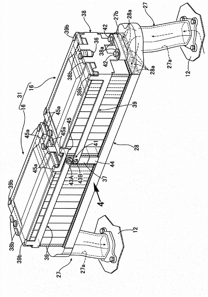
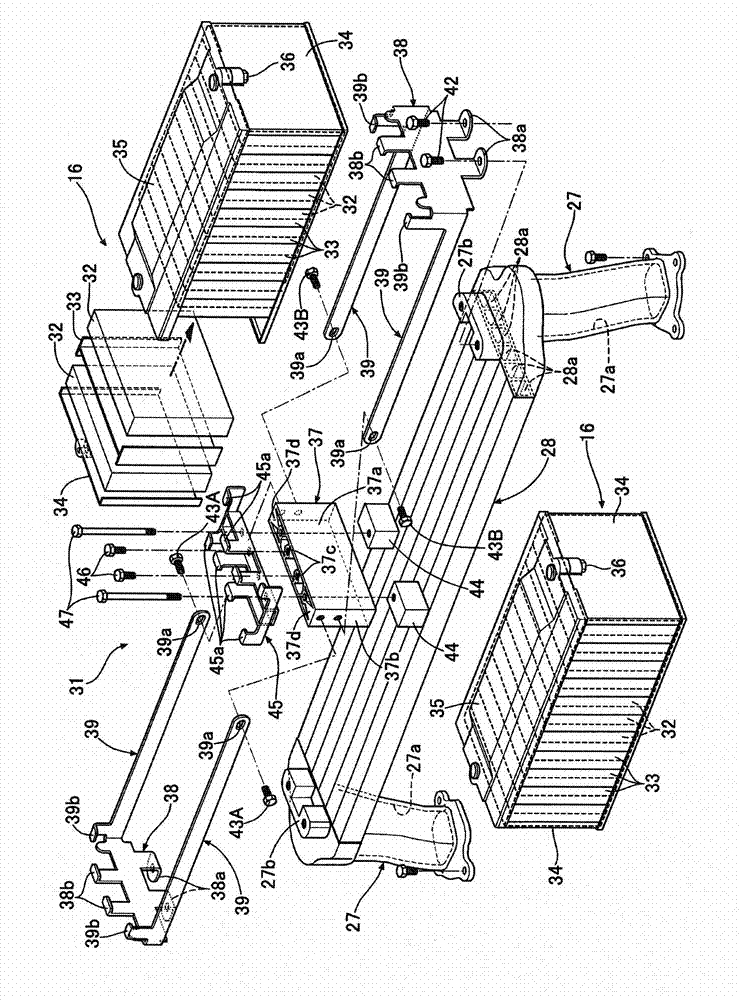
At this time, if bolts and nuts are used to fix the fixing member for fixing the battery module to the battery module support member, the bolts and nuts protrude into the refrigerant passage and block the flow of refrigerant, which may cause cooling of the battery module. reduced performance

Method used


Image

  • Fixing structure of battery module
  • Fixing structure of battery module
  • Fixing structure of battery module

Examples


Embodiment Construction

[0032] Below, according to Figure 1 to Figure 6 Embodiments of the present invention will be described.

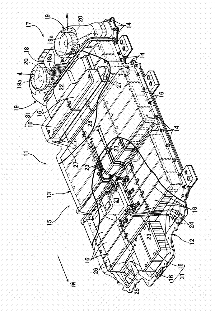
[0033] Such as figure 1 As shown, the battery pack 11 of an electric vehicle is equipped with a battery case 15 in which a synthetic resin battery cover 13 is combined with a synthetic resin battery cover 13 on the upper surface of a metal battery tray 12 and fastened and connected by bolts 14 . . . A plurality of battery modules 16 . . . are mounted on the upper surface.

[0034] The cooling device 17 provided at the rear of the battery pack 11 includes a suction duct 18 disposed in the center in the vehicle width direction, and a pair of left and right discharge ducts 19 disposed on both sides of the suction duct 18 in the vehicle width direction. A cooling air inlet 18 a is opened forward on the upper front surface of the suction passage 18 , and the cooling air inlet 18 a is used to suck air outside the battery pack 11 into the inside as cooling air. In addition, e...


PUM


Abstract

The invention relates to a fixing structure of a battery module, whereby the battery module is fixedly disposed on a supporting member without hindering the flowing of the refrigerant in the refrigerant pathway of the supporting member. A first end plate (37) disposed on the battery module (16) and the fastening member (44) disposed on the supporting member (28) are fixedly connected together by using the bolt (47). The battery module (16) is fixedly disposed on the supporting member (28), the refrigerant flowing in the refrigerant pathway (28a) in the supporting member (28) can be used to cool the battery module (16). At the same time, the fastening member (44) can be fixedly disposed on the surface of the supporting member (28) in a welded or bonded manner, therefore the fastening member (44) cannot be influenced by the flowing of the refrigerant in the refrigerant pathway (28a) in the supporting member (28), and the cooling performance of the battery module (16) can be guaranteed.

Description

technical field [0001] The present invention relates to fixing a battery module in which a plurality of battery cells are stacked on a support member having a refrigerant passage formed therein, whereby a first fixing member provided on the battery module and a first fixing member provided on the battery module are connected by a fastening member. The second fixing member on the supporting member fastens the fixing structure of the connected battery modules. Background technique [0002] According to the following patent document 1, there is known a structure in which the battery unit group is supported on the upper surface of the heat sink covering the upper surface opening of the box-shaped partition wall, and the cooling air is cooled by cooling air inside the partition wall. The passage flows, thereby cooling the heat-generating battery cell group with the cooling air. [0003] 【Prior technical literature】 [0004] 【Patent Literature】 [0005] [Patent Document 1] Japa...

Claims


Application Information

Patent Timeline
Patent Type & Authority Applications(China)
IPC IPC(8): H01M2/10H01M10/60H01M10/613H01M10/625H01M10/647H01M10/6565
CPCY02E60/10
Inventor 片山吾一高桥正树
Owner HONDA MOTOR CO LTD
Why Eureka
Eureka Blog
Learn More