Network voltage reactive-power compound coordination control system and method for new energy power generation

A coordinated control system and voltage reactive power technology, applied in the field of voltage reactive power control, can solve problems such as difficulty in achieving precise control, affecting the normal operation of the automatic voltage control system of the power grid, and voltage reactive power fluctuations.

Active Publication Date: 2013-06-19
NORTH CHINA ELECTRIC POWER UNIV (BAODING) +1
View PDF4 Cites 17 Cited by
  • Summary
  • Abstract
  • Description
  • Claims
  • Application Information

AI Technical Summary

Problems solved by technology

However, the main problems in the existing VQC device and the control strategy of the "nine-area map" are: the adjustment of the on-load tap changer transformer tap and the capacitor bank are adjusted in steps, and the adjustment steps are relatively large, making it difficult to achieve precise control. In addition, when the control strategy of the nine-zone diagram is adopted, oscillations will occur in some control areas, resulting in the traditional VQC device not being able to effectively meet the voltage and reactive power fluctuations caused by intermittent new energy generation such as wi

Method used


Image

  • Network voltage reactive-power compound coordination control system and method for new energy power generation
  • Network voltage reactive-power compound coordination control system and method for new energy power generation
  • Network voltage reactive-power compound coordination control system and method for new energy power generation

Examples


Embodiment Construction

[0098] The present invention will be further described below in conjunction with the accompanying drawings and specific embodiments.

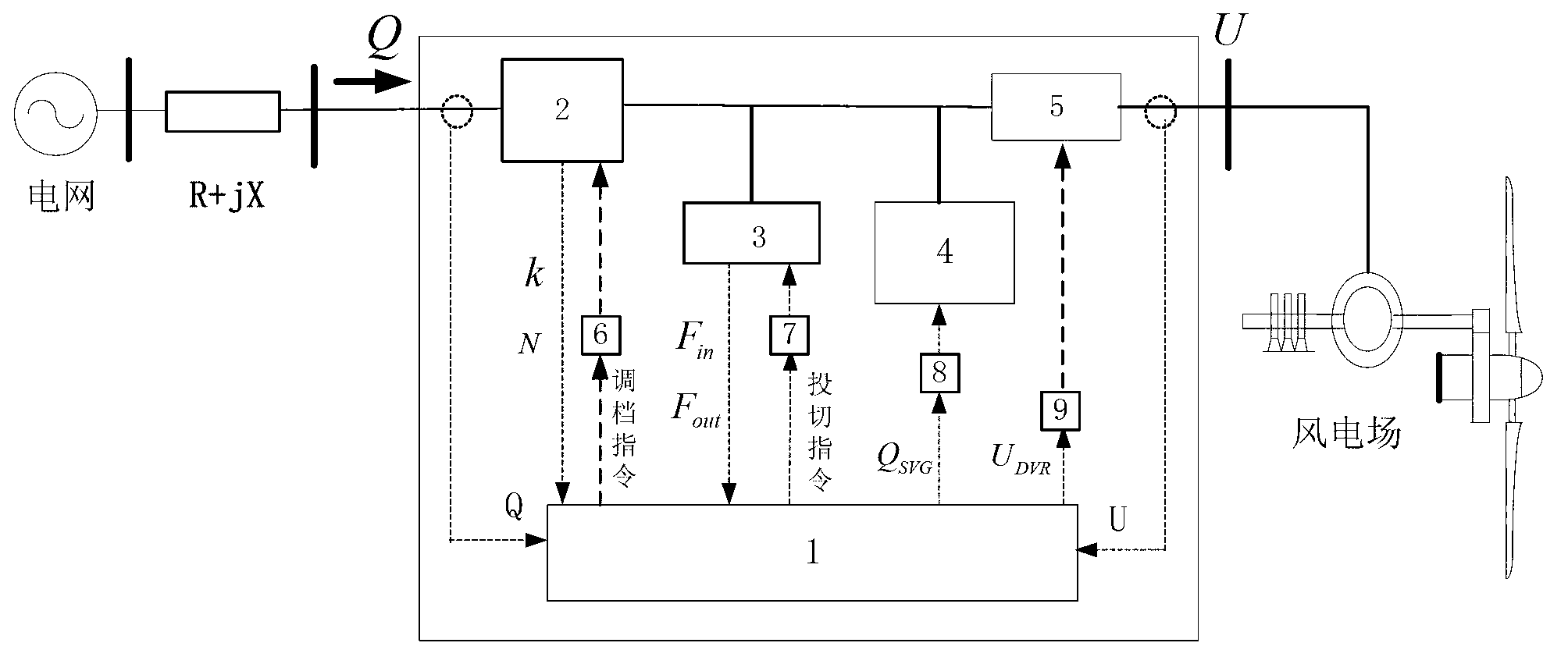
[0099] Such as figure 1 As shown, the existing substation voltage and reactive integrated control device VQC includes a capacitor bank and an on-load voltage regulating transformer, while the present invention combines a static dynamic var generator (Static Var Generator-SVG), a dynamic voltage restorer (Dynamic Voltage Restorer-DVR) combined with the existing substation voltage and reactive comprehensive control device VQC constitutes a dynamic voltage and reactive power control system DVQC, in which the on-load tap changer 2 is connected in series with the dynamic voltage restorer 5, the capacitor bank 3 and the static type The dynamic var generator 4 is connected in parallel with the on-load tap changer 2 and the dynamic voltage restorer 5 respectively, the first power amplifying unit 6, the second power amplifying unit 7, the third power am...


PUM


Abstract

The invention belongs to the technical field of voltage reactive-power control of grid-connected operation of new energy power generation with wind power, photovoltaic and the like in electric engineering, and particularly relates to a network voltage reactive-power compound coordination control system and method for new energy power generation. A silent dynamic var generator, a dynamic voltage restorer and an existing transformer station voltage reactive-power comprehensive control device are combined to form a dynamic voltage reactive-power control system, a voltage reactive-power plane is divided into sixteen control areas by the aid of the optimum voltage reactive-power operating state and the unit adjustment variable quantity of a capacitor bank and an on-load voltage regulating transformer tap, and each area corresponds a corresponding control strategy. Network voltage reactive-power frequent fluctuation caused by wind power and photovoltaic intermittent power generation is restrained by coordinately controlling the dynamic voltage reactive-power control system, network voltage reactive-power comprehensive control level is improved, practical engineering application is facilitated, and key technical support is provided for voltage reactive-power comprehensive control of new energy grid-connected power generation in a smart grid.

Description

technical field [0001] The invention belongs to the technical field of voltage and reactive power control for grid-connected power generation and operation of new energy sources such as wind power and photovoltaics in electrical engineering, and in particular relates to a grid voltage and reactive power composite coordinated control system and method including new energy power generation. Background technique [0002] The basic execution unit of the grid automatic voltage control system (Automatic Voltage Control System—AVC) is the substation voltage and reactive power comprehensive control device (Voltage and Reactive Power Control System—VQC). The VQC device is mainly composed of capacitor banks and on-load tap changer transformers. The VQC system coordinates and controls the switching of the capacitor bank and the transformation of the on-load tap changer (On Load Tap Changer—OLTC) through the control strategy of the nine-zone diagram to realize the comprehensive control o...

Claims


Application Information

Patent Timeline
IPC IPC(8): H02J3/12H02J3/18
CPCY02E10/76Y02E40/30
Inventor 李鹏薛金明王旭斌李涛信鹏飞李家明潘永忠陈建杰
Owner NORTH CHINA ELECTRIC POWER UNIV (BAODING)
Why Eureka
Try Eureka