Water spray head
A technology of sprinkler heads and sprinkler holes, which is applied in fire rescue and other directions, can solve the problems of increasing capacity, increasing splashing distance, increasing spraying pressure and spraying volume, etc. Effect
- Summary
- Abstract
- Description
- Claims
- Application Information
AI Technical Summary
Problems solved by technology
Method used
Image
Examples
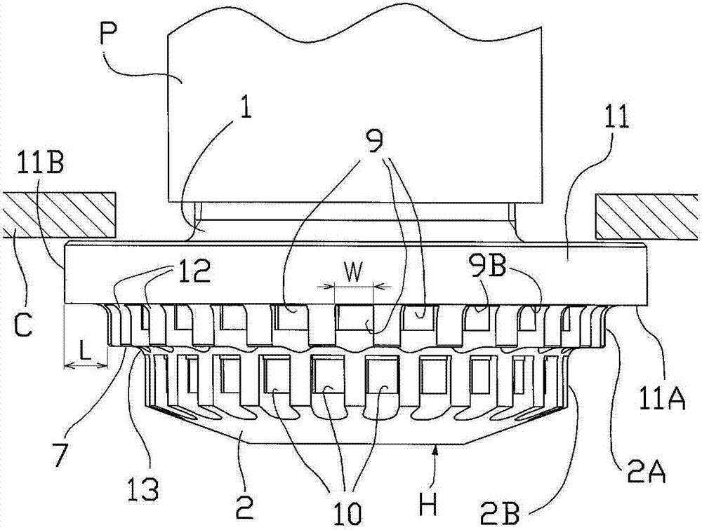
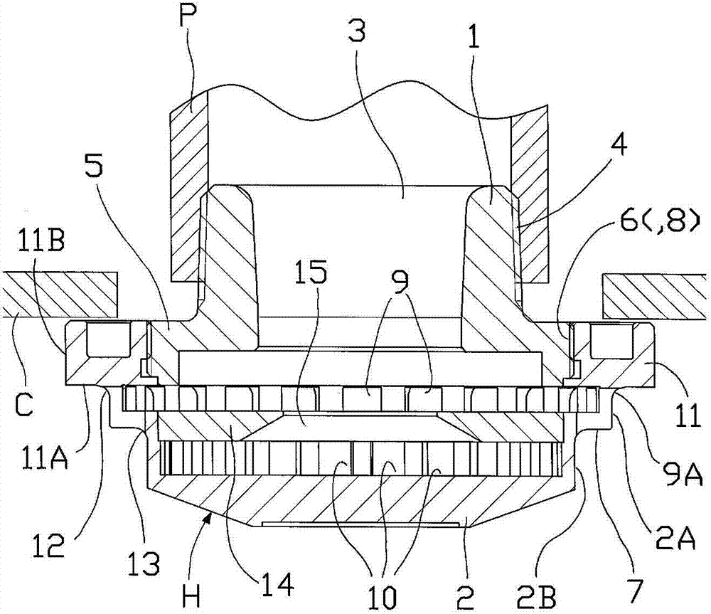
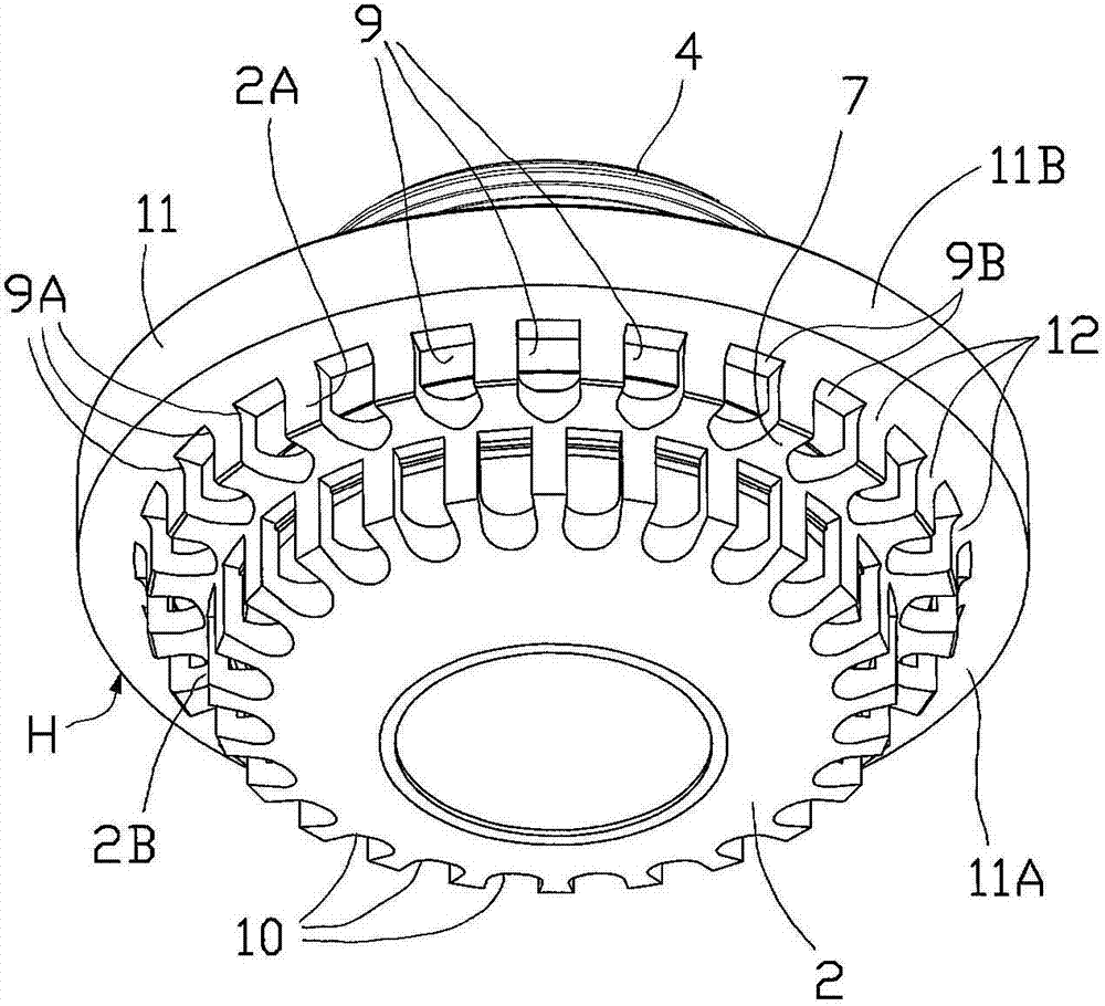
no. 1 approach ( pic 1 to pic 3
[0032] The sprinkler head H of the first embodiment is composed of a main body 1 and a deflector 2 . The main body 1 has a cylindrical shape, and a water outlet 3 is formed in the center, and a mounting screw 4 for mounting on a pipe P is provided on the outside of the water outlet 3 . A flange 5 is formed on the lower portion of the main body 1 , and an external thread 6 is provided on the outer peripheral portion of the flange 5 .
[0033] The deflector 2 is formed in a bowl shape having a stepped portion 7 on the outer periphery thereof, and a female thread 8 is provided on the upper inner periphery of the deflector 2 . The deflector 2 is attached to the main body 1 by screwing the internal thread 8 to the external thread 6 of the flange 5 of the main body 1 . A plurality of water spray holes (upper water spray holes) 9 are arranged in an annular arrangement above the step portion 7 on the deflector 2 . In addition, a plurality of water spray holes (lower layer water spra...
Deformed example 1
[0041] Variation 1 ( Figure 4 )
[0042] exist Figure 4 In Modification 1 shown, the lower surface 11A of the flange portion is inclined upward (in the direction of the ceiling C) from the upper spray hole 9 toward the outer edge portion 11B of the flange portion 11 . The outer edge portion 11B of the flange portion 11 is arranged close to the lower surface of the ceiling C, so as to reduce the resistance of the water flowing through the flange portion 11 to the lower surface of the ceiling C, thereby increasing the splashing distance in the horizontal direction. .
[0043] In addition, when the ceiling C is not provided, when the water sprayed from the upper water spray hole 9 flows along the lower surface 11A of the flange portion 11 and splashes from the outer edge portion 11B, it forms a water flow obliquely upward and splashes. It is thereby possible to increase the splash distance in the horizontal direction.
Deformed example 2
[0044] Variation 2 ( Figure 5A , 5B )
[0045] In Modification 2, a groove G is provided on the lower surface 11A of the flange portion 11 from the outlet of the upper spray hole 9 toward the outer edge portion 11B of the flange portion 11 . As a result, the water sprayed from the upper water spray hole 9 flows along the groove G, so that the amount of water sprayed in any direction can be increased or the splashing distance can be increased.
[0046] exist Figure 5A Among them, a groove G is provided in any direction on the lower surface 11A of the flange portion 11 . This guides the water flow along the direction in which the groove G extends, so that an elliptical protected area can be formed. In addition, in Figure 5B In the center, a groove G curved in an arc shape is provided, and the water sprayed from the upper spray hole 9 flows along the groove G, and the water splashed from the outer edge portion 11B is sprayed while swirling in a spiral shape. Thereby, the...
PUM
 Abstract
Description
Claims
Application Information
 - R&D
- Intellectual Property
- Life Sciences
- Materials
- Tech Scout
- Unparalleled Data Quality
- Higher Quality Content
- 60% Fewer Hallucinations
Browse by: Latest US Patents, China's latest patents, Technical Efficacy Thesaurus, Application Domain, Technology Topic, Popular Technical Reports.
© 2025 PatSnap. All rights reserved.Legal|Privacy policy|Modern Slavery Act Transparency Statement|Sitemap|About US| Contact US: help@patsnap.com


